 schlion
So now I had 6 TritiLEDs and was ready to calibrate them using the procedure described in Ted's corresponding build log. I applied the programming clip, uploaded the calibrator.hex file and measured the current.
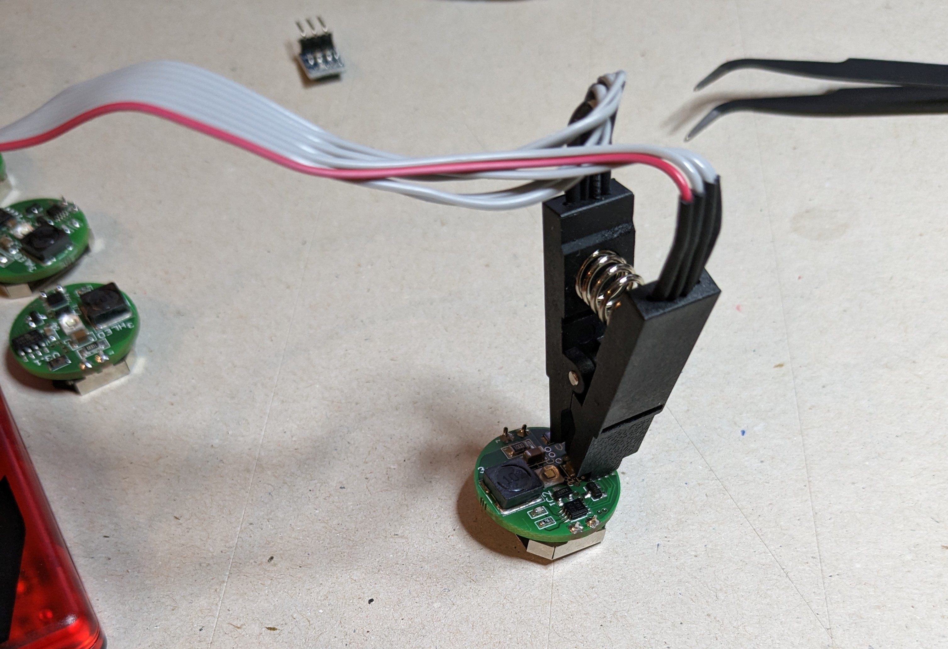
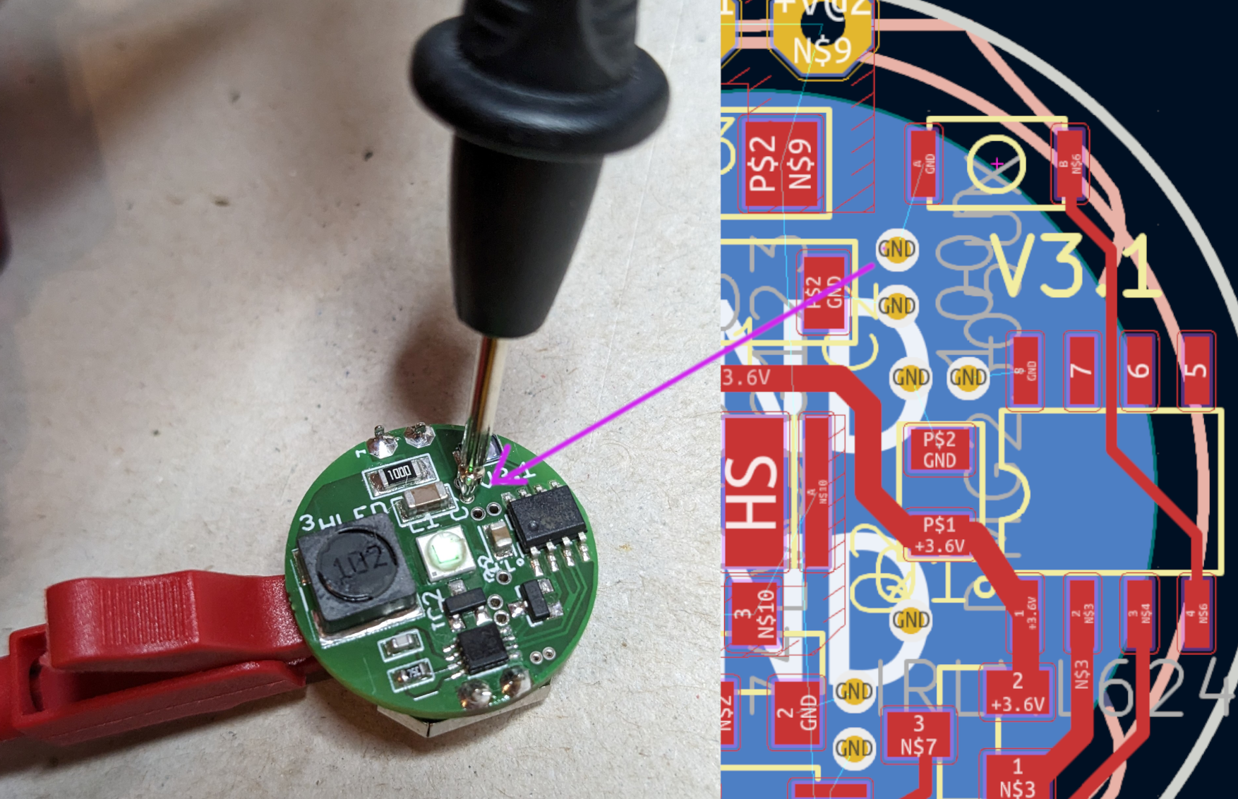
Here's my janky way of powering things, The vias (through holes) are connected to GND, that's why this worked, you can see it in the board view:
But instead of the 10.3, 19.4 and 37.7 µA @ 100, 200 and 400 Hz, I was getting more in the order of 94, 184 and 344 µA. At hat point I got stuck. I tried the other boards, but the power consumption was similar. I had noticed that the interactive BOM, I had generated from Ted's EAGLE file had a 100nF decoupling capacitor (C2) instead of a 1µF one. So, I tried switching it out and ended up breaking the capacitor because I did not manage to heat both side enough to desolder them at the same time. But instead of changing out C2 I exchanged C3, the enegry-storing 10µF capacitor. And this did lower the current, but not enough. I would still need to drive the LED at well below 50Hz to even get to a year. This, of course, means a blinking LED rather than a dimly glowing on. So, I commented on the Calibration log and slept on it. The next day, Ted himself answered and suggested that I probably mounted my LED the wrong way, driving it directly when the monostable was on and not powering it via the inductor. This also explained the better performance without the 10 uF capacitor.
So it was hot sand pan time again! I de-soldered the battery clip, heated up my sand, put some flux around the LED, waited for the solder to melt and turned the LED around 180°. This was pretty difficult working over a hot pan without magnification. On two PCBs, I didn't get it quite right and had to reflow them again, but in the end, all of my 6 TritiLED were working as expected, consuming around 13, 25 and 49 µA. After that I used up the rest of my components to make the remaining 5 tritiLEDs, this time doing everything right from the start. Here are the final currents draws for the XPE2 LED:
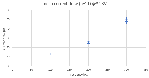
| Hz | 1 | 2 | 3 | 4 | 5 | 6 | 7 | 8 | 9 | 10 | 11 | mean | std |
| 100 | 13.70 | 13.60 | 11.40 | 13.40 | 12.80 | 13.90 | 12.40 | 13.75 | 14.7 | 12.6 | 12.6 | 13.17 | 0.91 |
| 200 | 26.20 | 25.80 | 21.70 | 25.40 | 24.30 | 26.70 | 23.70 | 26.20 | 28.1 | 24.1 | 23.95 | 25.10 | 1.8 |
| 300 | 50.90 | 50.30 | 42.10 | 49.40 | 47.40 | 52.00 | 46.10 | 51 | 54.8 | 47.1 | 46.65 | 48.89 | 3.5 |
I then put all the currents in the currents.dat file, ran the calibrator with
python .\calibrate.py
and compiled everything with
& "C:\Program Files\Microchip\MPLABX\v6.10\gnuBins\GnuWin32\bin\make.exe" tritiled_v30_selectable_runtime
Then I tested the every one of them to see if they were working properly. For one of the PCBs, I had to reflash it.
At last comes the cleanup, of both my workbench, but also all the flux residue.I used 99% isopropyl alcohol and cotton swabs. But found out that holding a small piece of tissue with my tweezers was much more suitable for getting into narrow channels around the LED. I've also seen people use paint brushes. I should get some of those.
Discussions
Become a Hackaday.io Member
Create an account to leave a comment. Already have an account? Log In.