bornach
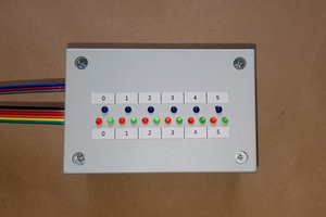
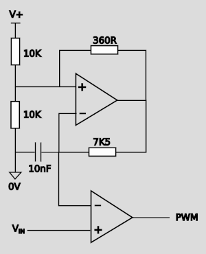
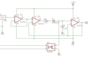
Here is the simple op-amp oscillator circuit that I started with:

Using an op amp as a comparator the voltage of the capacitor can be compared with an input control voltage to generate a pulse width modulated signal

The same oscillator can be shared with multiple comparators and so it is fairly straightforward to create an RGB LED dimmer device. The resulting circuit has 3 potentiometers and 4 op amps. 5 op amps if you use 2 op amps in the oscillator to get better shaped triangular waves - 1 op amp becomes a Schmitt trigger and the other an integrator.
To reduce the number of potentiometers to just one, while still being able to select an interesting range of colours, requires adding a few more op amps to the mix.

The 10K potentiometer on the left will be the main controller. The two 5K trim pots are used to tune the shape of the voltage function that will be mapped to the main 10K potentiometer. The scale trim pot adjust the slope of the voltage ramp. The output of the inverting op amp saturates at either end, so adjusting this reduces the distance over which the wiper on the 10K pot has to move to select the full range of pulse widths. The translate trim pot is used to adjust where along the 10K potentiometer the voltage ramp begins.
For a voltage ramp that increases instead of decreasing when the 10K potentiometer wiper is moved in a given direction, another inverting op amp stage can be inserted, or the inputs of the comparator can be swapped.

When swapping comparator inputs the oscillator output will now have to be inverted to ensure that all PWM signals stay in phase -- this will be necessary for the next step which involves combining PWM signals together using boolean logic.

Combining two PWM signals using an OR gate is equivalent to applying a Max(a,b) function. I've used diode logic for this. I found that no op amp buffer was required between the OR-gate and the NPN transistor base.
I could have used AND or OR gates from (7400 or 4000 series logic chips), but I thought it would be interesting to take a more "purest" approach with op amps being the only ICs used. An added bonus is that we are no longer restricted to 5V logic. We could drive 12V RGB LED strips with this circuit powered on the same rail.
And likewise the AND gate is equivalent to a Min(a,b) function. In this case, the op amp buffer is required. The diode AND-gate alone was unable to pull the NPN transistor base voltage below 0.7V so the transistor would never switch off.
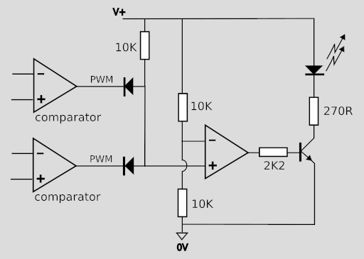
The op amp stage wired as a comparator applied a threshold to the output of the diode AND-gate. Since I'm using LM358s even with a single-sided supply voltage the output of the op amp is still capable of pulling the base-emitter voltage close to ground.
By combining voltage ramps of various shapes with min-max functions we can define different control voltage profiles for the red, green, and blue channels


 Electroniclovers123