Close
0%
0%

Op Amp Based Lithium Charger

A linear CC-CV charger to handle various secondary lithium chemistries. Built with Op Amps and Comparators.

Similar projects worth following
An early design of this project was itself used in my bachelor's senior project, and now the goal is to create a more complete charger in line with current lithium chargers.

On this website you will find many kinds of Lithium battery charger projects. The plain fire hazards, the abuse of LM317s and TL431s that don't quite regulate, the one-chip-on-a-board project. In this project I would like to explore what it takes to charge a lithium chemistry secondary (rechargeable) cell, and how to implement it.

It doesn't take too much to pull it off, we can make due with the components of yesteryear. Op Amps, Comparators, Latches, No microcontrollers necessary!

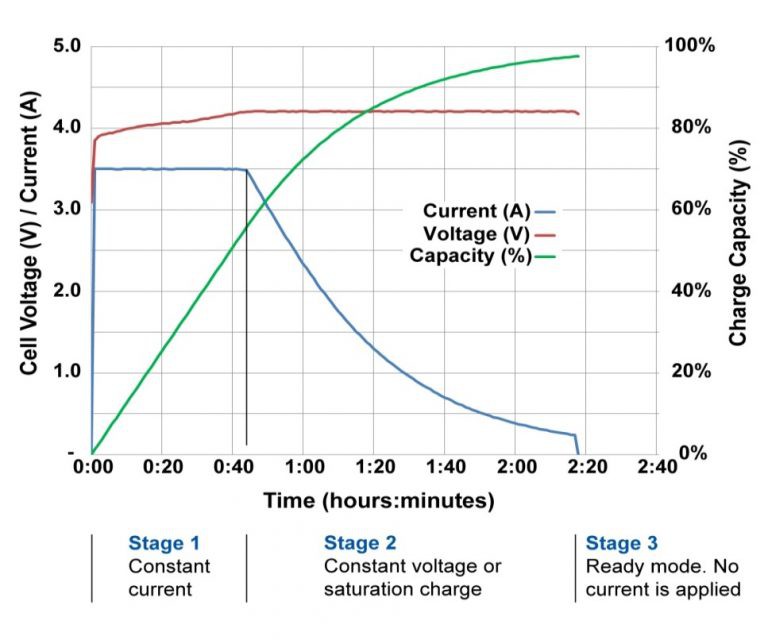
To begin this project I'd like to give an overview of the process of charging Lithium batteries of various chemistries. There are two primary phases in charging a lithium battery: A Constant Current phase (CC), and a Constant Voltage phase (CV). A discharged battery will be fed a constant current until the battery measures a pre-determined voltage, at which point that voltage is held while the current drops to a pre-determined value related to a battery's rated capacity. Once this point has been reached, the battery is considered charged and the charger that is connected should not pass any additional current into the battery.

A figure of the process occurring with a Li-ion cell. A battery is formed from one or more cells.

In the roughly 30 years that lithium batteries have been on the commercial markets, several types of lithium chemistries fulfill most of the world's demand (described as the compound of the cathodes): Lithium Cobalt Oxides (LCO), Lithium Nickel Manganese Cobalt (NMC), Lithium Nickel Manganese Oxide (NMO), Lithium Iron Phosphate (LFP), etc... In this list all but the LFP chemistries can be charged surpassing 4.1 volts (LFP at roughly 3.6V), the absolute latest designs can withstand a CV set point of 4.4V! Most chemistries are considered discharged below 3.0 volts.

With advances in the design of lithium batteries, in addition to the slow increase in capacity, a tradeoff can be made in how fast a lithium cell can be charged. Higher charge and discharge rates for a small sacrifice in capacity. We label charge/discharge rates with a "C" nomenclature. This "C" rating is linearly proportional to the capacity of a battery, e.g. A 2 amp-hour (Ah) battery charging at 1C has 2 amps going into it.
A large portion of charging ICs for the consumer market are designed to charge batteries roughly around 0.5-1C. Also, a battery charging at a rate of 1C means 100% of the battery's capacity is put into it in one hour, A rate of 2C would mean the battery was charged at twice the rate (finished in half an hour).

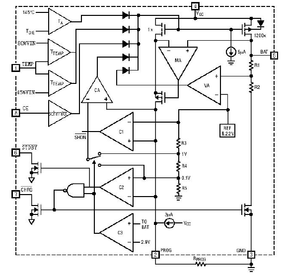
And to begin with describing how a lithium charger is designed, let's look at common examples. The hobbyist market has been dominated with very inexpensive chargers based on the TP4056, designed by Top Power ASIC. This is a linear charger which is mainly designed for a 5V input and charges batteries to roughly 4.2V (not for LFP chemistries) at rates of up to 1.2A.
A block diagram of the device can be found online, and here is a copy for reference. This will provide a solid foundation for creating a CC-CV charger of our own.

TP4056 Datasheet, Page 7

A second reference is a Microchip brand charger, the MCP73831. This IC is also a linear charger. Several options of output voltage exist (from 4.2 to 4.5V) and can output up to 500mA. The datasheet contains a useful block diagram as well.

MCP73831 Datasheet, Page 2

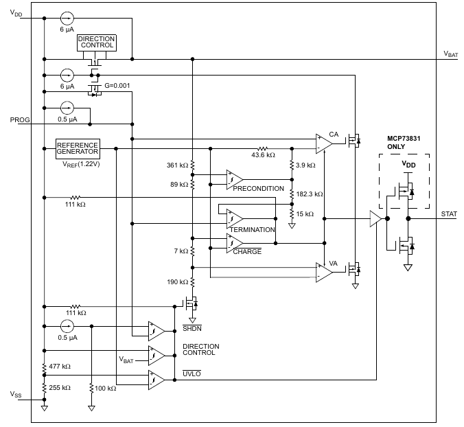
Both ICs have similar structures. Externally, both ICs have a single resistor which programs the CC stage. There is a means to display the state of the charger through one or more LEDs. The pass transistor, which sits between the battery and the input supply voltage both seem to want to be turned on hard, and are put into regulation by Op Amps. I want to highlight how unintuitive this form of regulation sounds with an comparison. We drive our cars with out feet on the pedals. Press down on the accelerator and our car goes faster. This IC of a car has a brick on the pedal and the Op Amps make it go slower by lifting the brick up.

Whatever current is going through the pass transistor is mirrored through another transistor in the IC. Not 1:1 mirroring, but a small fraction (1:1000 in the MCP IC, 1:1200 in the TP IC). This fraction goes through the PROG pin to ground. i.e. 1200mA going into the battery means 1mA is going through the resistor on the PROG pin, and that voltage generated on the resistor is tied to the inputs of several internal Op Amps. While the current mirror approach is elegant, it cannot...

Read more »

app.py

Python script to generate new analog gauge scale marks. Import into google sheets to add text. Found at: https://community.element14.com/technologies/open-source-hardware/b/blog/posts/meter-dial-creator-toolkit

py - 4.42 kB - 06/12/2023 at 06:35

Download

battery charger V2A1E1.zip

Hopefully Sanitized Project Files. Made with KiCad 7.0.5.

x-zip-compressed - 1.20 MB - 06/12/2023 at 06:03

Download

Battery Charger V1A4.pdf

NPN Darlington Config for Pass Transistor. Op Amp Comparator and Latch. May not work, included to showcase concepts.

Adobe Portable Document Format - 91.04 kB - 06/12/2023 at 05:31

Preview
Download

Battery Charger V2A1E1 Schematic.pdf

NPN Darlington Config for Pass Transistor. Comparator and Latch made with LM339. PCB in project is based off this design. Adjust R7-9 to control C-rate shutoff.

Adobe Portable Document Format - 100.80 kB - 06/12/2023 at 05:27

Preview
Download

  • Analog Meters

    ROFLhoff07/10/2023 at 22:55 0 comments

    In this update I will talk about how I added analog gauges into my project to easily display the charging progress of connected batteries.

    I did not originally have analog gauges for this project. I had a couple 16x2 LCD displays but I was firm on not incorporating a microcontroller into this project. So I went and looked on amazon for gauges. I wasn't sure what I was going to find. Most gauges were listed as measuring very small amounts of current (tens to hundreds of microamps), and it turns out this is the most common and versatile kind.

    These gauges use a "D’Arsonval" movement, which operate using small currents and also have enough delay in movement that there is signal averaging builtin, for free.

    I picked two gauges that were labeled 500uA full scale, and the scales were labeled to be used to directly measure that current. My plan is to make new plates to show proper scales.

    Both gauges will be measuring voltages in circuit, and not currents, so the gauges must be configured. This is done through a series resistance between the measured voltage and the gauge. To calculate what resistance is needed, we can use the following equation:

    where V_fs is the maximum voltage to measure, i_fs is the given full scale current, and R_internal is a property of the specific gauge. This value is pretty small compared to R_series so it can be omitted with the understanding that the gauge will swing close to, but not to its maximum.

    The meter that is measuring current will see at most 5V, we find that the series resistance is a simple 10K ohms (ignoring R_internal).
    The other gauge that is going to measure the battery voltage will be slightly trickier to setup. If the gauge is connected the same way as the current gauge, and if the practical range seen will be from 3V to 4.3V, this is going to be a rather narrow section of the gauge. It would be nice to utilize more real estate to make the battery voltage easier to read at a glance.

    Signal Conditioning is another good use of Op Amps. We can take the battery voltage and do both offsetting and scaling so that we get the most of the usable deflection range. The following diagram is the Op Amp configured to both offsetting and scaling using common resistor values.

    This particular Op Amp configuration is mentioned in a fantastic Texas Instrument document called "Op Amps for Everybody" in section 4.2, Figure 4-8. The following section goes over the equations to convert offset/scaling to resistor ratios. Do keep in mind that the LM358 is not a rail-to-rail Op Amp, and the output cannot reach the positive supply voltage.

    In my situation, I wanted to take an input voltages of 2.5-4.6V and have the Op Amp output ideally 0-500uA. In our case we can get away with generating an output voltage and passing that to a gauge with a series resistance to properly set the full scale reading. We can implement an acceptable design with E12 value resistors. The input of the amplifier is best connected to the V_sns signal.

    Not shown is a 3k9 resistor from the amplifier output to the 500uA meter for the voltage gauge. This lets the roughly 1.85V output of the amplifier result in full scale movement on the gauge.

    What comes next is creating a custom scale for the gauge instead of seeing "0-500uA" as the output.

    Looking online, I found resource from element14, where a user named shabaz created a python script that make a custom scale. It's the file named "app.py" in this project. I had tweaked it to make markings in roughly 100mV steps from 3.0V all the way to 4.6V, with thicker markings for important levels like 3.0V, 3.6V(safe LFP voltage), and 4.2V(safe Li-po voltage).
    The problem is that these markings had to line up with the full scale of the gauge. My calibration procedure was to:

    1. Connect a variable voltage source to the input of the Op Amp Circuit, and an ammeter to the output of the circuit.
    2. Set the input to 2.9V and increasing in 100mV steps, measure the output current.
    3. In the...

    Read more »

  • The 4-ish Stages of a CCCV Charger

    ROFLhoff06/22/2023 at 05:09 0 comments

    The posted schematic is the version I created a PCB design with, and sent to a fab company to produce samples of. Part designations will be referenced to this schematic unless a new design succeeds this version.

    The basic principle of this design is a combination of 4 parts:

    • Pass Transistor(s)
    • Constant Current (CC) Amplifier
    • Constant Voltage (CV) Amplifier
    • Shutoff Latch/Comparator

    And auxiliary components like voltage references, switches, fans and heatsinks.

    1. The Pass Transistor(s)

    To keep with the theme of creating a working design with simple and widely available components, this design will start with an NPN BJT Darlington Pair. This will create a couple limitations in the design. First off, the TIP series of Darlington Pairs have extra resistors and a diode built-in that simplify using the device as a switch. The following image shows the internal construction:

    The problem lies in the diode. If a battery is connected to the charger and the power is disconnected, the Op Amps and TL431 regulator will now be back-powered from the connected battery. This has the potential to drain the battery. A quick fix is to simply add a forward-biased diode between the Darlington Pair and the current sense resistor R22. This diode leads me to bring up another point.

    To drive this Darlington Pair in the active region, the base pin will sometimes need to be driven to voltages that the LM358 output stage can barely reach. To properly estimate the needed base voltage, we need to get the worst case condition. This occurs at the switch between the CC and CV stage in charging. The battery is at its highest voltage, and the voltage developed across R22 is greatest. To put into equation form, this appears as:

    When I had configured my charger (supplied with 12.2V) to charge an 8.4V 2S lipo battery at 2 Amps, I noticed that the charger could not sustain 2A when the battery voltage got higher than roughly 8.2V. I figured that the base pin was not being driven hard enough, so I had temporarily replaced the base drive resistor R1 with a lower value.

    Looking at the TI datasheet for the LM358, it is stated that the output can't get any closer than about 1.5V from the positive rail. Given that in the current design, there is an additional forward-biased diode that controls the base pin, this lets the Op Amp output control a slightly higher voltage of 0.8V away from the positive supply.

    We can bandaid fix this problem by running the charger at a higher voltage, but since this is a linear charger, this is a waste of power and users would need a bigger heatsink to compensate. Not a real solution. The proper fix is to design the base pin to be controller with lower voltages. A PNP darlington pair or P-channel MOSFET would make better pass transistors.

    Be sure to connect a heatsink and fan to whatever pass transistor you use. The peak power that is wasted is:

    When charging a 1S lipo battery at 2A, the pass transistor was producing over 16W of heat at peak. I used a heatsink originally used to cool an old Celeron 366MHz CPU, it came with a fan plus mounting bracket for active cooling, and it handled the load with no issues. I could touch the heatsink and not burn my fingers.

    2. Constant Current Amplifier

    Op Amps U2B, U3A, and U3B form the CC amps.

    U2B is converting the voltage across the current sense resistor R22 and generating a single-ended output signal on R15. The output equation for this amplifier is:

    In my design R15, R18, and R22 are selected such that 1A going through R22 generates 1V across R15. This allows an intuitive link between the measured current and the current set point. The voltage that is generated through the potentiometer RV2 is buffered through U3B. Since RV2 is connected straight across a 5V reference, this potentiometer will allow the user to adjust the charger to send up to 5A into the battery. This is a rather high amount of current compared to the cheap commercial offerings, but some component...

    Read more »

View all 2 project logs

Enjoy this project?

Share

Discussions

Kuba Sunderland-Ober wrote 06/07/2023 at 21:19 point

I call such projects the "domesday" designs. If the parts for this are no longer available, we don't need to be worried about technology all that much - we'll be scavenging for food :) Conversely, the parts for this design can be bought mostly anywhere. It's a great analog design learning tool as well. I'm glad someone did it :)

  Are you sure? yes | no

Similar Projects

Does this project spark your interest?

Become a member to follow this project and never miss any updates