 ROFLhoff
In this update I will talk about how I added analog gauges into my project to easily display the charging progress of connected batteries.
I did not originally have analog gauges for this project. I had a couple 16x2 LCD displays but I was firm on not incorporating a microcontroller into this project. So I went and looked on amazon for gauges. I wasn't sure what I was going to find. Most gauges were listed as measuring very small amounts of current (tens to hundreds of microamps), and it turns out this is the most common and versatile kind.
These gauges use a "D’Arsonval" movement, which operate using small currents and also have enough delay in movement that there is signal averaging builtin, for free.
I picked two gauges that were labeled 500uA full scale, and the scales were labeled to be used to directly measure that current. My plan is to make new plates to show proper scales.
Both gauges will be measuring voltages in circuit, and not currents, so the gauges must be configured. This is done through a series resistance between the measured voltage and the gauge. To calculate what resistance is needed, we can use the following equation:

where V_fs is the maximum voltage to measure, i_fs is the given full scale current, and R_internal is a property of the specific gauge. This value is pretty small compared to R_series so it can be omitted with the understanding that the gauge will swing close to, but not to its maximum.
The meter that is measuring current will see at most 5V, we find that the series resistance is a simple 10K ohms (ignoring R_internal).
The other gauge that is going to measure the battery voltage will be slightly trickier to setup. If the gauge is connected the same way as the current gauge, and if the practical range seen will be from 3V to 4.3V, this is going to be a rather narrow section of the gauge. It would be nice to utilize more real estate to make the battery voltage easier to read at a glance.
Signal Conditioning is another good use of Op Amps. We can take the battery voltage and do both offsetting and scaling so that we get the most of the usable deflection range. The following diagram is the Op Amp configured to both offsetting and scaling using common resistor values.
This particular Op Amp configuration is mentioned in a fantastic Texas Instrument document called "Op Amps for Everybody" in section 4.2, Figure 4-8. The following section goes over the equations to convert offset/scaling to resistor ratios. Do keep in mind that the LM358 is not a rail-to-rail Op Amp, and the output cannot reach the positive supply voltage.
In my situation, I wanted to take an input voltages of 2.5-4.6V and have the Op Amp output ideally 0-500uA. In our case we can get away with generating an output voltage and passing that to a gauge with a series resistance to properly set the full scale reading. We can implement an acceptable design with E12 value resistors. The input of the amplifier is best connected to the V_sns signal.
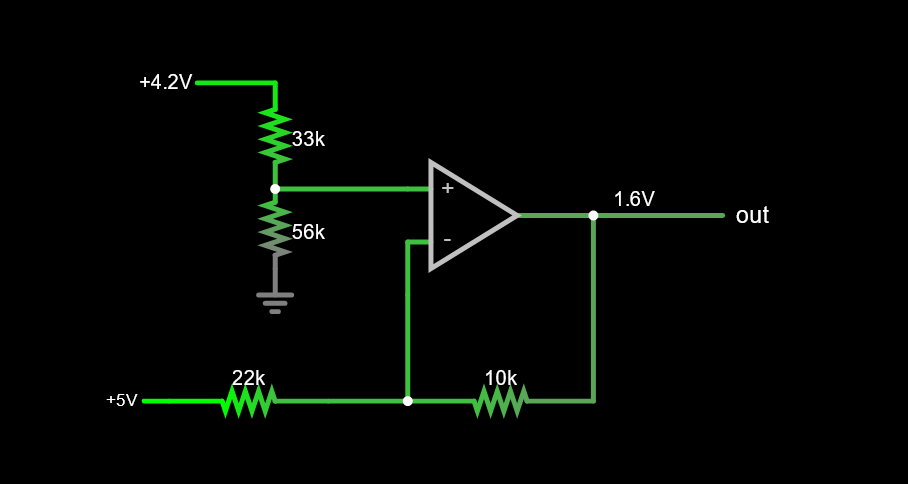
Not shown is a 3k9 resistor from the amplifier output to the 500uA meter for the voltage gauge. This lets the roughly 1.85V output of the amplifier result in full scale movement on the gauge.
What comes next is creating a custom scale for the gauge instead of seeing "0-500uA" as the output.
Looking online, I found resource from element14, where a user named shabaz created a python script that make a custom scale. It's the file named "app.py" in this project. I had tweaked it to make markings in roughly 100mV steps from 3.0V all the way to 4.6V, with thicker markings for important levels like 3.0V, 3.6V(safe LFP voltage), and 4.2V(safe Li-po voltage).
The problem is that these markings had to line up with the full scale of the gauge. My calibration procedure was to:
1. Connect a variable voltage source to the input of the Op Amp Circuit, and an ammeter to the output of the circuit.
2. Set the input to 2.9V and increasing in 100mV steps, measure the output current.
3. In the code, set each mark to the measured current.
4. Run the code, a svg file should be created.
5. Open the svg file in an editor and add text as desired.
6. Print the finished scale, and affix it to the gauge.
My calibration table looked like this:
4.6v = 488uA
4.5v = 469uA
4.4v = 448uA
4.35v= 434uA
4.3v = 425uA
4.2v = 402uA
4.1v = 378uA
4.0v = 357uA
3.9v = 333uA
3.8v = 312uA
3.7v = 285uA
3.6v = 262uA
3.5v = 240uA
3.4v = 220uA
3.3v = 190uA
3.2v = 168uA
3.1v = 149uA
3.0v = 124uA
2.9v = 100uA
This Op Amp circuit works fairly well, the usable voltage range had expanded and centered on the gauge.
In the centerpiece image for this project, both analog gauges are displayed in action. The green battery is in the constant current stage of charging, and the CC mode LED was on to confirm it. There was 1 Amp going into the battery, and the current battery voltage was nearly 4.0V. A nice unintended effect with the amplifier was that when the battery was removed, the needle on the gauge hovered in the zone before the 2.9V tick. This is a handy way to note that the device was on and no battery was attached. When the device was turned off and had no battery connected, the needle was all the way to the left.
In the next post, the gauge circuitry will be modified so that a button can toggle the gauges to show either the Current/Voltage setpoints, and the Battery Current/Voltage levels.
Discussions
Become a Hackaday.io Member
Create an account to leave a comment. Already have an account? Log In.