 chris
chrisIntroduction and goals
This is a pH meter with temperature compensation and digital readout (but no microcontroller): plug a standard glass-electrode pH probe into the BNC jack and use it to measure the pH of a solution.
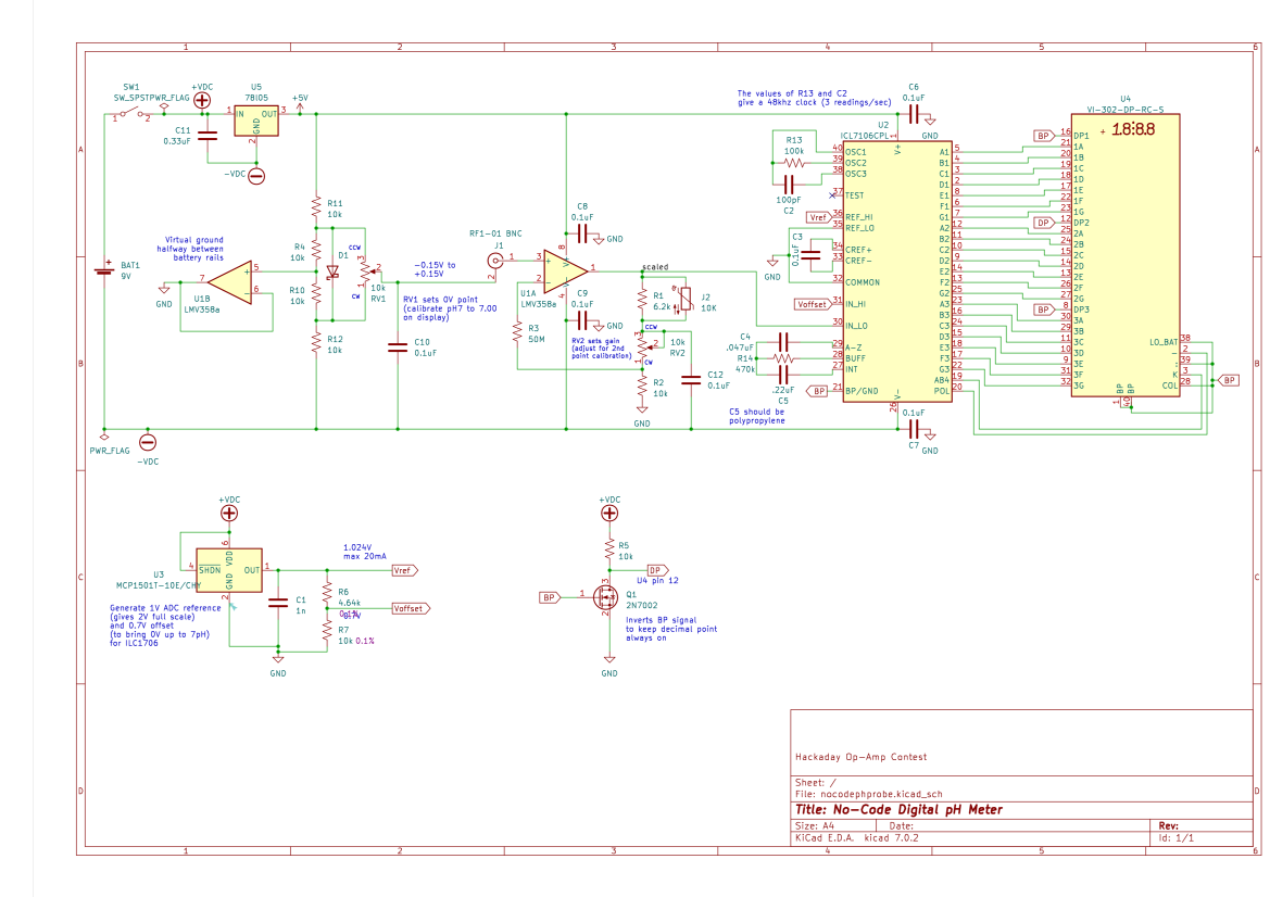
This project is part of Hackaday's 2023 Op-Amp Challenge to create some kind of precise, creative, or classic circuit that uses op-amps in 8 weeks. Here we use an lmv358a op-amp to amplify the signal from a pH probe and then display it on an LCD via an 7106 "3 1/2 Digit A/D Converter". No software.
Two potentiometers allow for 2-point calibration of the probe. An optional temperature probe (just an NTC soldered to a 1/8" audio plug) provides some temperature compensation. The prototype PCB (drawn in KiCad and manufactured by JCLPCB) fits into a nice off-the-shelf enclosure from Polycase complete with 9V battery holder.
The up-to-date KiCad schematic and other files are available on github:
https://github.com/cristoper/nocodephmeter
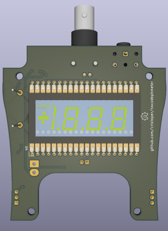
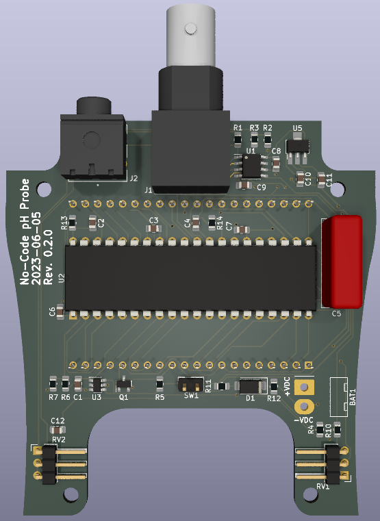
Rendering of top and bottom of PCB (see below for some photographs):
What is all this pH stuff anyhow?
pH
pH is a standard scale from 0 to 14 that measures the acidity (hydrogen ion activity) of a solution. Low values are acidic, high values are basic, and a pH of 7 is neutral (like pure water). The pH is defined as the negative log of the hydrogen ion activity, so each pH value indicates 10 times greater hydrogen ion activity than the next biggest integer value. For example, a pH 6 indicates 100 times the hydrogen ion activity of a pH 8.
pH has a wide range of applications in industry and DIY experimenting. In my case I have a garden bed that I mulch every year with pine needles from a nearby pine tree, which I've heard can make the soil more acidic. The idea that pine needles can measurably alter the soil acidity is apparently a common misconception, but either way I'm curious to measure the pH of my garden.
See also Wikipedia's Soil pH.
pH Probe
The standard way to measure pH is with two electrodes: one kept at a reference pH and a lithium-implanted glass electrode put in contact with the solution to test. The hydrogen ions interact with the glass electrode and the voltage generated between the electrodes is (inversely) proportional to the pH of the test solution:
or
Where
pH is pH of test solution
V is voltage across the probe electrodes
F is the Faraday constant = 9.648533e4 C/mol
R is the molar gas constant: 8.314510 J/K*mol
T is temperature in K: 273 + degrees C
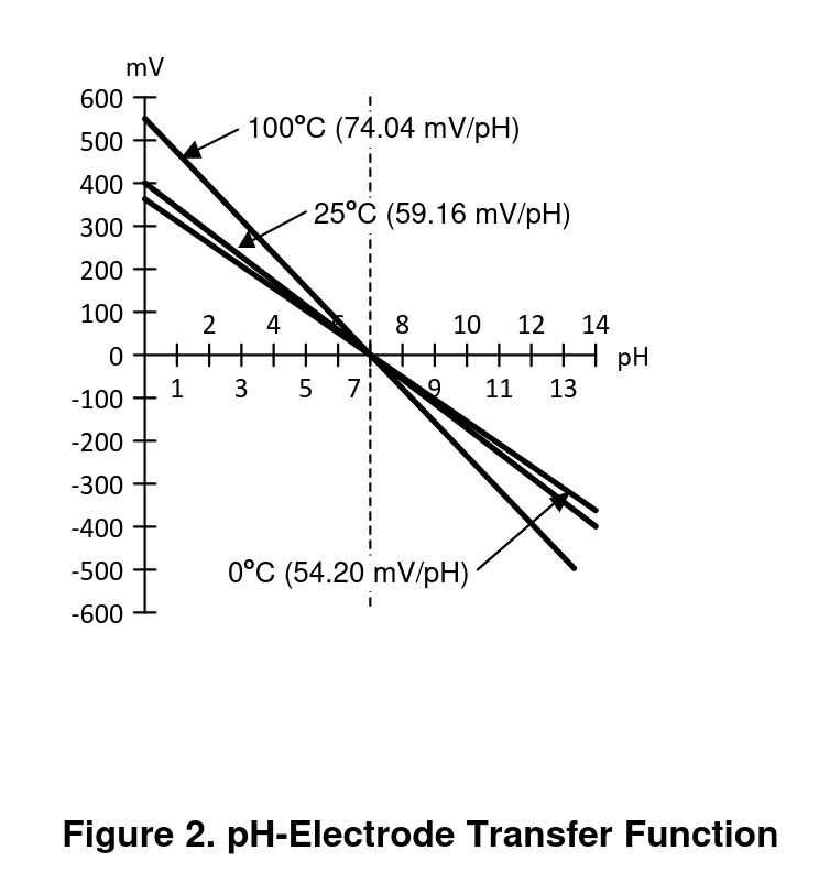
This means that at 25C, each change in pH is proportional to 59.13mV for a full-scale input of +/- 414mV.
Additionally, the relationship between pH and voltage changes with temperature (at higher temperatures the same pH produces higher magnitude voltages). Figure 2 of the app note AN-1852 Designing With pH Electrodes illustrates the relationship between voltage and pH well:
Another useful app note is CN-0326 Isolated Low Power pH Monitor with Temperature Compensation
pH probes can be expensive and even good probes need to be calibrated regularly and only last for a few years of use. More expensive probes are more sensitive (faster response time), more accurate (better reference electrode), and are built to last longer. The probe I bought to test my pH meter with is the "Lab Grade pH Probe" form Atlas Scientific. However, less expensive probes are available from places like amazon.com and probably fine for most home and hobbyist use cases.
pH Meter
A pH meter takes the voltage from a pH probe and displays it to the user as a pH value. This usually involves amplifying the voltage, reading it into a microcontroller via an ADC, calculating the equivalent pH, performing calibration and temperature compensation on the value, then displaying it to the user.
In keeping with the analog-centric nature of the op-amp challenge, I thought it would be fun to avoid microcontrollers for this project. This often means saving time on writing code and spending more time learning how to use obsolete, expensive ICs instead. In this case an ICL7106 "3 1/2 Digit A/D Converter" which is an analog-to-digital converter and segmented LCD driver in one big 40-pin DIP. (The ICL7106 -- and the 7107 for segmented LED displays -- is used in many panel voltmeters and is still produced and easy to get.)
Goals
I had several personal and technical goals in mind with this project.
Personal
Despite being interested in electronics from a young age, I've never really completed any prototypes and it has been years since I've tried to design or breadboard anything. I took the Op-Amp challenge as an opportunity to dive back in to the electronics hobby.
- Complete a prototype that [mostly] works
- Learn how to use KiCad (this is my first KiCad project)
- Layout and have a PCB manufactured for the first time!
- Hand solder surface-mount components for the first time!
Technical
- Accurately measure pH to 0.05 over most of the 0-14 range and a temperature range of about 10C-30C or more.
- 2-point calibration (zero offset and scale). These should be *independent* calibration points: that is, changing the scale should not require the user to go back and reclibrate the zero offset.
- Make it fit in a nice-looking enclosure
Circuit Description
Overview
To convert the voltage produced by the pH probe (eg, 118.26mv) into a voltage that can be read as a pH value (eg, 5.00), the meter needs to perform the following (assuming 25C):
Vout = (Vin - bias) * -1.69 + 0.7V
- Offset any bias in the probe and amplifier so that a pH of 7 results in 0V out of the amp
- Scale the voltage so that it can be displayed at 2V fullscale as a pH value. In other words, at 25C every 59.13mV should be scaled to 100mV: a gain of 1.69
- Invert the signal because pH is inversely proportional to voltage
- Add 700mV to bring 0V up to 7 pH
- Display the result on a LCD via the ICL7106 A/D converter
Amplifier selection
The heart of the circuit, and the star of the Op-Amp Challenge, is the operational amplifier. pH probes generate relatively high voltage compared to many sensors (+/- 500mV), change slowly, and must be calibrated regularly anyway, so the demands on the op-amp are actually pretty modest. The biggest consideration is the very high output impedance of the glass electrode (I've read it can be as large as a gigaohm) which puts two major constraints on the choice of amp:
- It must have high input impedance (otherwise most of the signal would drop across the probe's output impedance). This means a FET-input amp.
- Its input bias current must be low enough that the input bias voltage can be compensated out
Assume a probe output impedance of 1G then an input bias current of 1nA would result in an offset error of 1V which is more than the entire fullscale input range (an error of over 16 pH)!
For this project I discovered and chose the LMV358A op-amp. It is similar to the classic LM358, but the two additional letters make a big difference:
- The "V" in LMV358A indicates it is the FET input version of the classic LM358
- The "A" in LMV358A is a version with much better input offset voltage (typically 1mV) and input bias current (10pA)
Better yet, the LMV358A's input offset current (the difference between the bias current in each input) is only 3pA -- that means much of the input bias current can be eliminated by putting a big resistor in the negative feedback path (R3) so that the voltage caused by the bias current will offset the voltage caused by the bias current through the pH probe.
I chose 50M for R3; the output impedance of the pH probe is probably higher than that, but I didn't know the consequences of using such a large resistor (leakage current noise, etc) so I chickened out of using anything larger.
Those offset voltage and bias current figures should be good enough for our applications. Worst case input voltage offset is 4mV and worst case offset from the input bias current is 1GOhm * 10pA = 10mV. So worst case we need to be able to compensate out only +/- 14mV from the input (less than +/- 0.25 pH) plus whatever offset the probe itself introduces (can be around 30mV).
The LMV358A's input offset figures are still not as good as most "precision" op-amps (though the 10pA input offset voltage beats some precision amps). But the LMV358A is available as an 8-pin dual op-amp for $0.44 USD in single quantities -- that's $0.22 per amp, probably 10x less than most precision amps! I'm happy to have found this part.
The LMV358A has a maximum supply voltage of 5.5V. The 7805 linear voltage regulator (U5) regulates the 9V down to 5V to keep it in its range.
Two-point calibration and the need for split rails
A design goal is to give the user independent two-point calibration. That means the user should be able to adjust out the input offset voltage *without* changing the gain of the meter and vice-versa. To accomplish that we need to keep the signal centered at 0V and only add the 700mV (to bring 0V up to 7 pH) after amplification. That implies operating the op-amp on positive and negative voltage rails.
To generate split rails from a single 9V batter, the single 5V from the 7805 regulator is divided in half with a resistor divider (R4,R10,R11,R12) and the mid-point of that divider is buffered by one of the LMV358A amps (U1B) to create a virtual ground. That gives about +2.5V and -2.5V relative to that ground.
Offset calibration
Offset calibration is done by applying +150mv to -150mv to the reference electrode of the pH probe. The required +/- 150mV reference is generated by D1, a Schottky diode across the voltage divider so that its forward voltage drop is centered at 0V. The offset potentiometer (RV1) can then be used to pick off the required offset voltage.
C10 decouples any noise picked up by the potentiometer wiper to the negative battery terminal. In my tests it is important to include.
Scale calibration
The gain required to convert the probe voltage to an accurate pH value depends on temperature. U1A is the LMV358A amp responsible for amplifying the signal from the pH probe. R1, R2, and RV2 set its gain. J2 is the optional temperature probe; assume it is not plugged in and absent from the circuit for now. With RV2 all the way counterclockwise the gain of U1A is 26.2/16.2 = 1.62. With RV2 all the way clockwise the gain is 16.2/6.2 = 2.6. That range allows calibrating the probe from 0C to about 50C.
C12 decouples any noise picked up by the potentiometer wiper to the negative battery terminal.
Temperature compensation
Calibrating the meter at one temperature and then measuring the pH of a solution at a much different temperature will result in inaccurate readings. To keep accuracy across a range of temperatures, we need some way to adjust the gain of the op-amp as the temperature of the test solution changes. The solution I came up with is to put an NTC across R1 so that as the temperature of the NTC increases, the gain of the amp also increases.
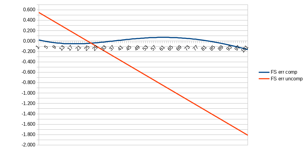
I chose a common value of NTC (10K with a beta of 3892K) and then used a spreadsheet (ntcvalue.ods in the git repo) to calculate the gain and error from 0C to 100C for a given value of R1. I then used LibreOffice Calc's "Goal Seek" tool to find a value of R1 that minimizes the error. 6.2K it is. The graph below shows the theoretical fullscale error (in pH) across temperatures with (blue line) and without (red line) temperature compensation.
I've not had time to test the actual accuracy achieved, but I like the simple, analog temperature compensation I came up with for this meter. And I like that it is optional, since most times I expect to calibrate and measure solutions at similar temperatures so I won't need to plug in the temperature probe.
The temperature probe is made from an NTC assembly (a Littlefuse USP10982) soldered to the tip and ring of an 1/8" audio plug.
Invert and make signal positive
The last step of the pH transfer function is to invert it and add 700mV offset to bring the entire range positive (to the 0.00v-1.40V range corresponding to 0-14 pH). We could do this with a third op-amp. However, that would introduce yet another source of offset voltage errors. Instead we invert the signal by applying it to the IN_LO (rather than the IN_HIGH) input of the ICL1706 A/D converter. We add the 700mV offset to the IN_HIGH input.
The 700mV offset is generated from a Microchip MCP1501 1.024V voltage reference (U3) divided down by R6 and R7. The accuracy of this 700mV is important, because any error here introduces a coupling between the offset and gain calibrations... a user would need to iterate between the two calibration knobs to calibrate out the error which is a hassle when you have to switch the probe between calibration solutions and wait 30 seconds for it to settle. For that reason we use 0.1% resistors in the divider.
Display
The voltage from the op-amp is converted to digital and displayed on a segmented LCD (U4, a VI-302 3 1/2 digit display by the ICL7106 (U2) which is an analog-to-digital converter and segmented LCD driver in one.
Other than the tricks above used to invert and offset the input voltage, the ICL7106 is configured according to the datasheet for 2V fullscale reading. C5 is the integration capacitor, which the datasheet said should be a polypropylene type to reduce errors from dielectric hysteresis. The most readily available polypropylene caps are big mains-rated filter caps, sot that's what I used.
The ICL1706 displays 2V fullscale, but we want to display pH from 0.00 to 14.00, so we need to hardwire the 2nd decimal point on. Segments on the LCD are visible when they are out of phase with the backplane. So to keep the decimal point always on, we use a simple transistor invertor (Q1, a common 2n7002 MOSFET) to drive that segment always out of phase with the backplane.
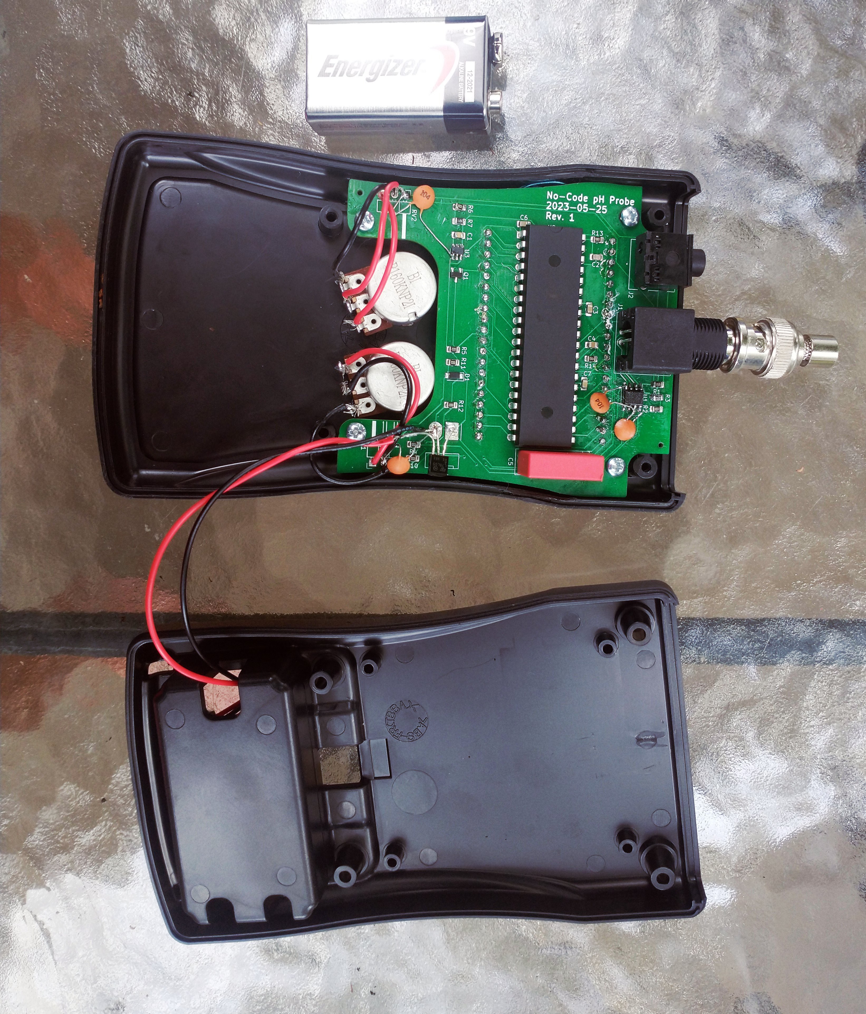
Prototype
After designing and drawing the circuit in KiCad, I chose an enclosure and then drew the PCB layout while selecting components on digikey. I started on the PCB only 2 weeks before the challenge deadline so I had to really rush to get the PCB done, sent to JLCPCB for printing, order all the components, enclsoure, and pH probe then build the prototype and finish this write up. The pH probe arrived the afternoon before the contest deadline so I couldn't test everything until the last minute.
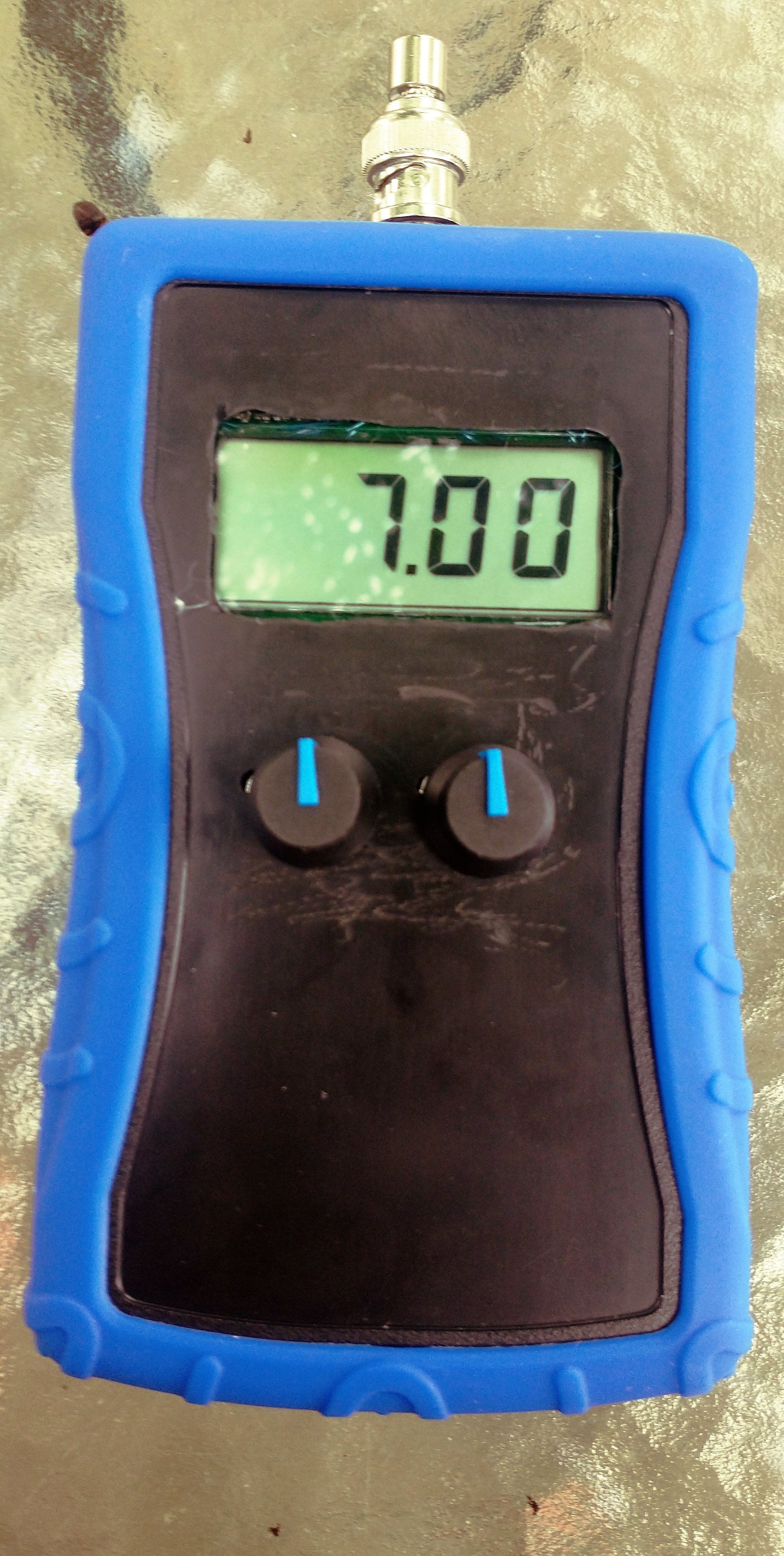
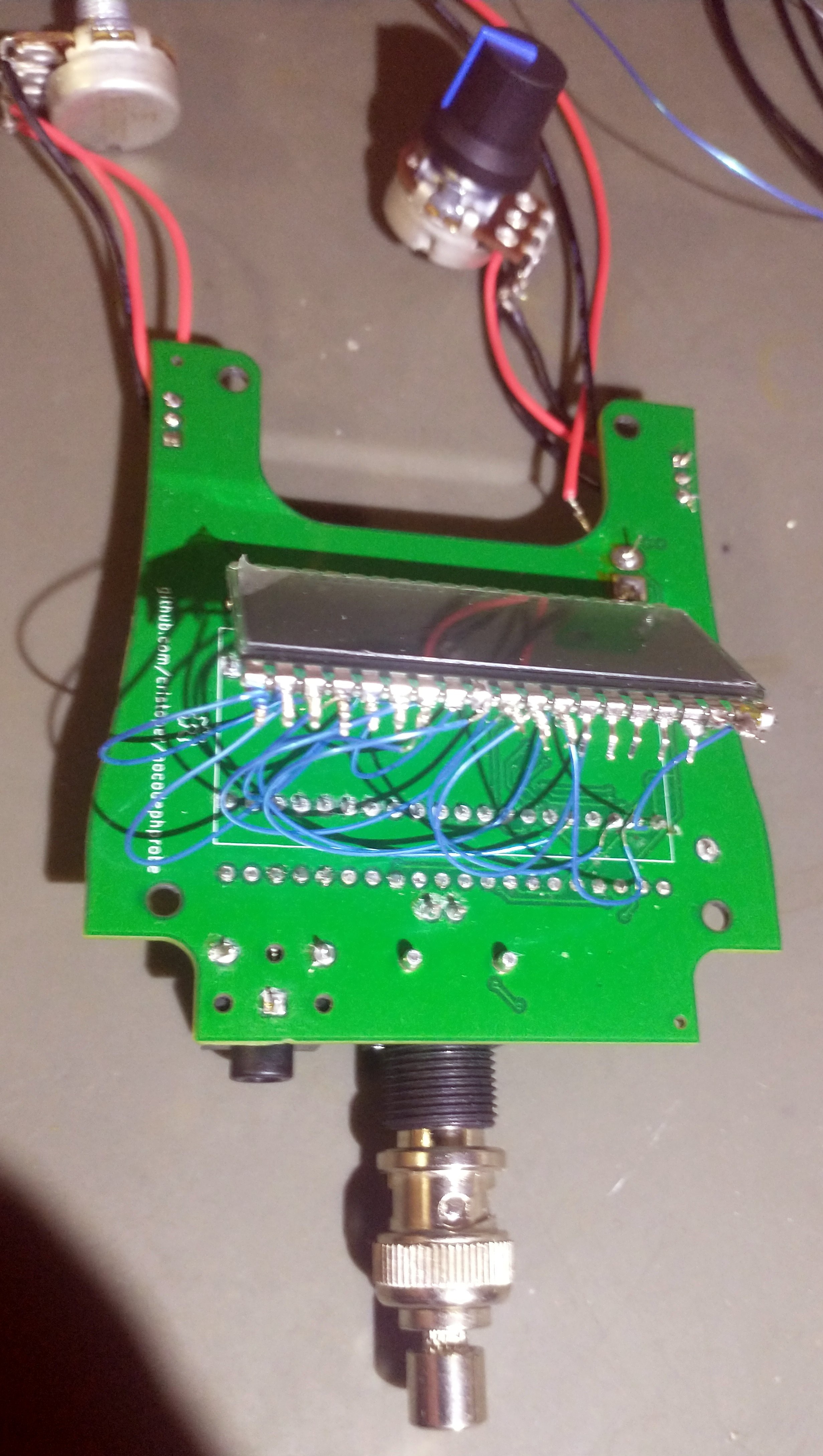
Image of the assembled prototype complete with rubber baby buggy bumper. (I used a 50 ohm terminator to test the display while I was waiting for the pH probe to arrive in the mail.)
Enclosure
I found the VM-series of "handheld plastic enclosures" from Polycase and they looked like what I had in mind for a case. They are also reasonably priced even for single quantities ($8.82 USD), include an option for a 9V battery compartment, have good technical drawings, and have an option for a rubber sleeve. I'm very happy to have discovered these. For this project I chose the VM-35 with 9V battery holder and recessed front panel.
I did a real hack job with a rotary tool to machine the rectangular cut out for the LCD and the holes for the potentiometers into the front panel of the enclosure. I drew and printed a template so I knew where to put the cut outs, but somehow things still didn't quite line up. For the next version I will find a neater and more accurate way to machine the front panel.
PCB
I drew the PCB outline in LibreCad to fit into the VM-35 case. I struggled with some of the curves because I could not tell from the drawings where the intersection points were... I eventually ended up with a board that fits well, but later I realized that Polycase provides both 3D STEP files and 2D DWG drawings that I probably could have used instead of manually drawing the board outline from the dimensions in the PDF drawing.
The PCB is a 2-layer layout with all the components on one side except for the LCD is on the top side. When the PCB is mounted in the case, the LCD is visible through the rectangular cut out in the case. I used connector footprints for the potentiometers and the battery connector, though in the prototype I just soldered the wires directly to the board.
I drew the footprint for the LCD display (to almost disastrous results; see below) but found a nice 3D model for a different LCD display in the KiCad library that fit. I also made the footprint and 3D model of the BNC jack (I modeled it in FreeCAD).
I used JLCPCB to have the board printed. And since it was so inexpensive I also had them solder on most of the surface mount passives. I then hand soldered everything else including the oddball R6 and R3, the lmv358a op-amp, mcp1501t voltage reference, and the 80 pins of through hole components. This was my first time attempting surface mount soldering and I had no flux (other than the flux in the core of my solder) on hand! I still managed to get the job done, but not as effortlessly or neatly as it could have gone.
Laying out the board in KiCad, having a 3D preview, and then having the board manufactured was a very fun experience, despite how many mistakes my first prototype boards had.
Operation
The prototype meter has a BNC jack and a 1/8" TRS jack at the top of the enclosure for the pH probe and optional temperature probe.
To calibrate and use:
- Plug the pH meter into the BNC jack at the top of the enclosure
- Optionally plug the temperature probe into the 1/8" TRS jack at the top of the enclosure
- Choose two values of pH calibration solution to calibrate the probe and meter. Preferably one of them should be 7.00 to set the zero point and the other should be either an acid or a base depending on what you expect to measure
- Place the probe in the 7.00 calibration solution and with RV2 in its center position adjust RV1 (the left knob) until the display reads "7.00"
- Place the probe in the second calibration solution. Let the display settle and then adjust RV2 (the right knob) until the display reads the correct value
- The probe is now calibrated. Place the probe in the test solution, allow it to settle (around 30 seconds) and read the pH value
Results
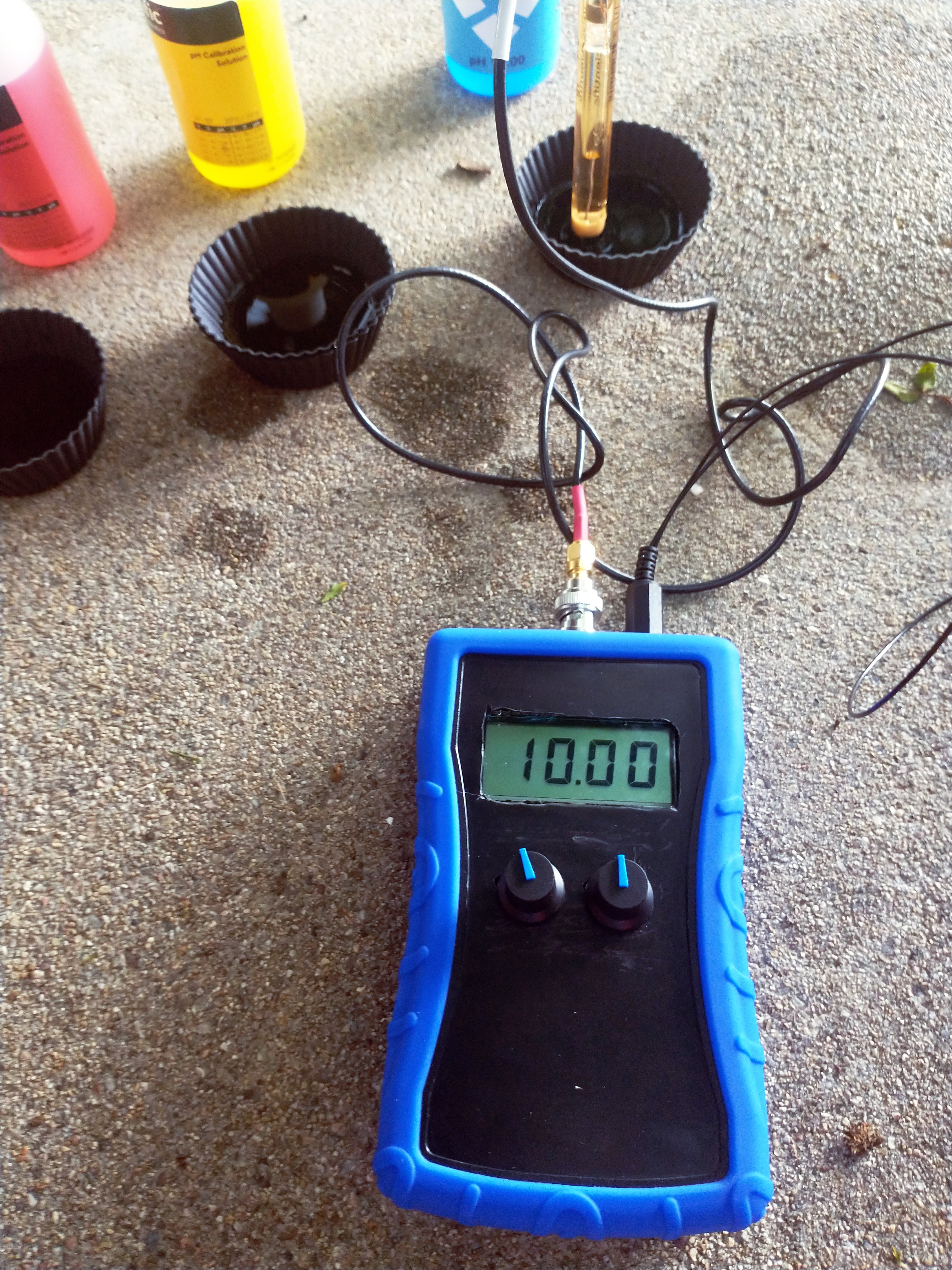
To test the prototype I ordered some pH calibration solution with my pH probe (4.00, 7.00, and 10.00). I calibrated with the 7.00 and 10.00 and tested against the 4.00.
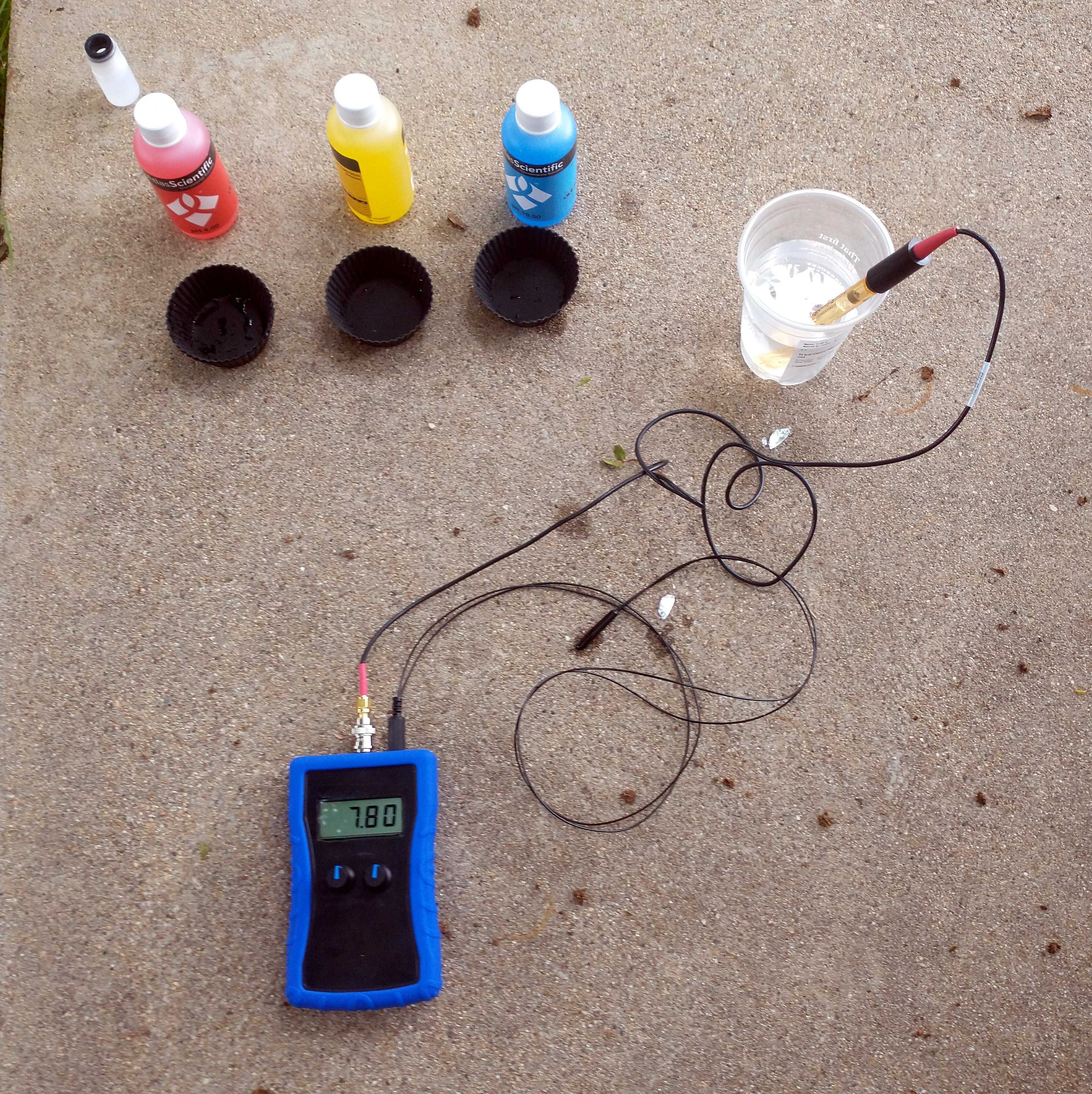
[In the image above you can see my test set up. The pH probe is in some water used to rinse the calibration solutions after each measurement. The NTC temperature probe is also plugged in to the meter.]
After setting the zero point to 7.00, and keeping RV2 in its center position, the meter read almost right on for the 10.00 solution! That was encouraging.
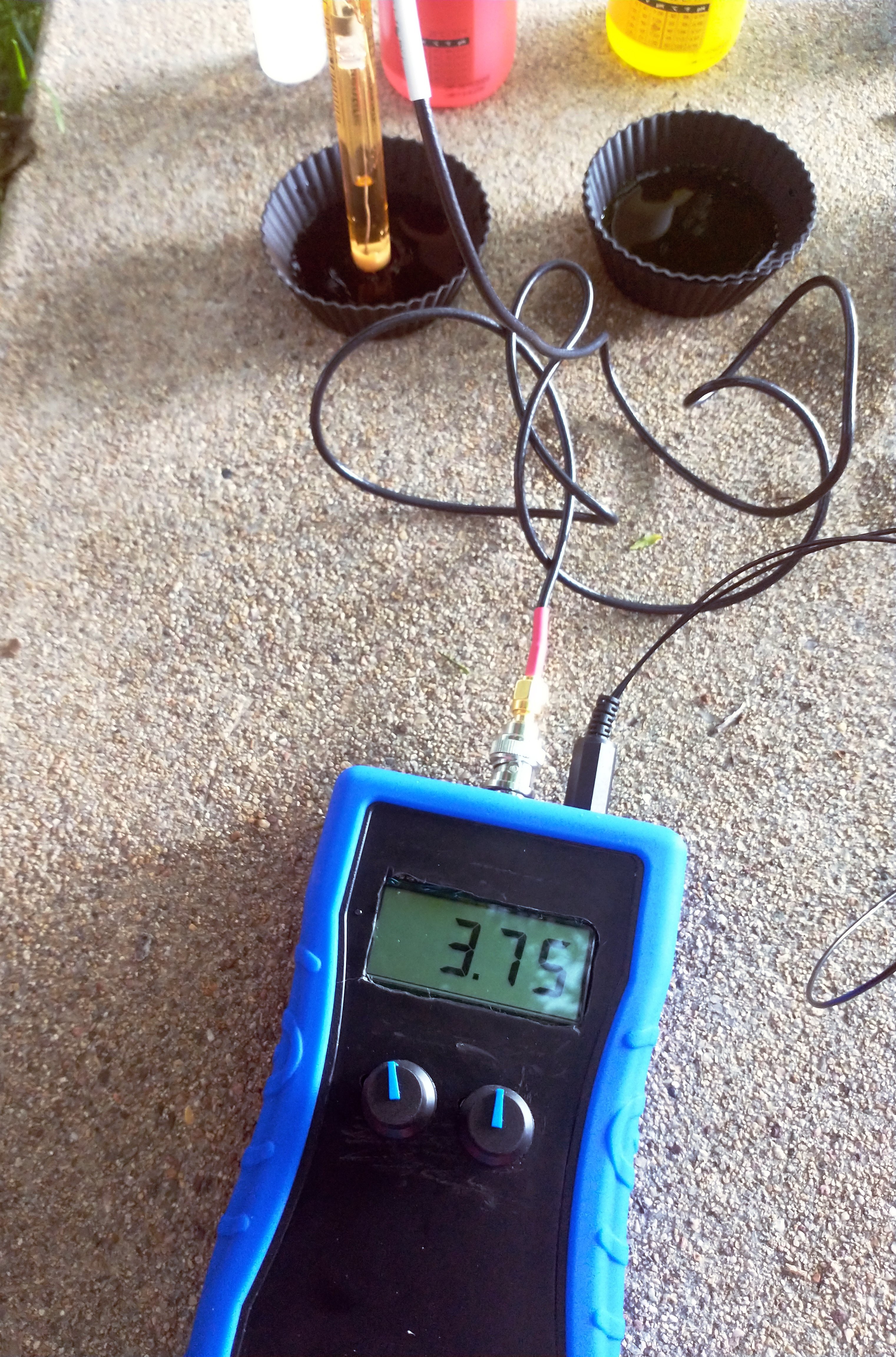
However, when I then placed the probe in the 4.00 solution the meter under read to as much as 3.75. I got similar results with and without temperature probe plugged in. That is quite a bit worse than the +/- 0.05 pH I was going for.
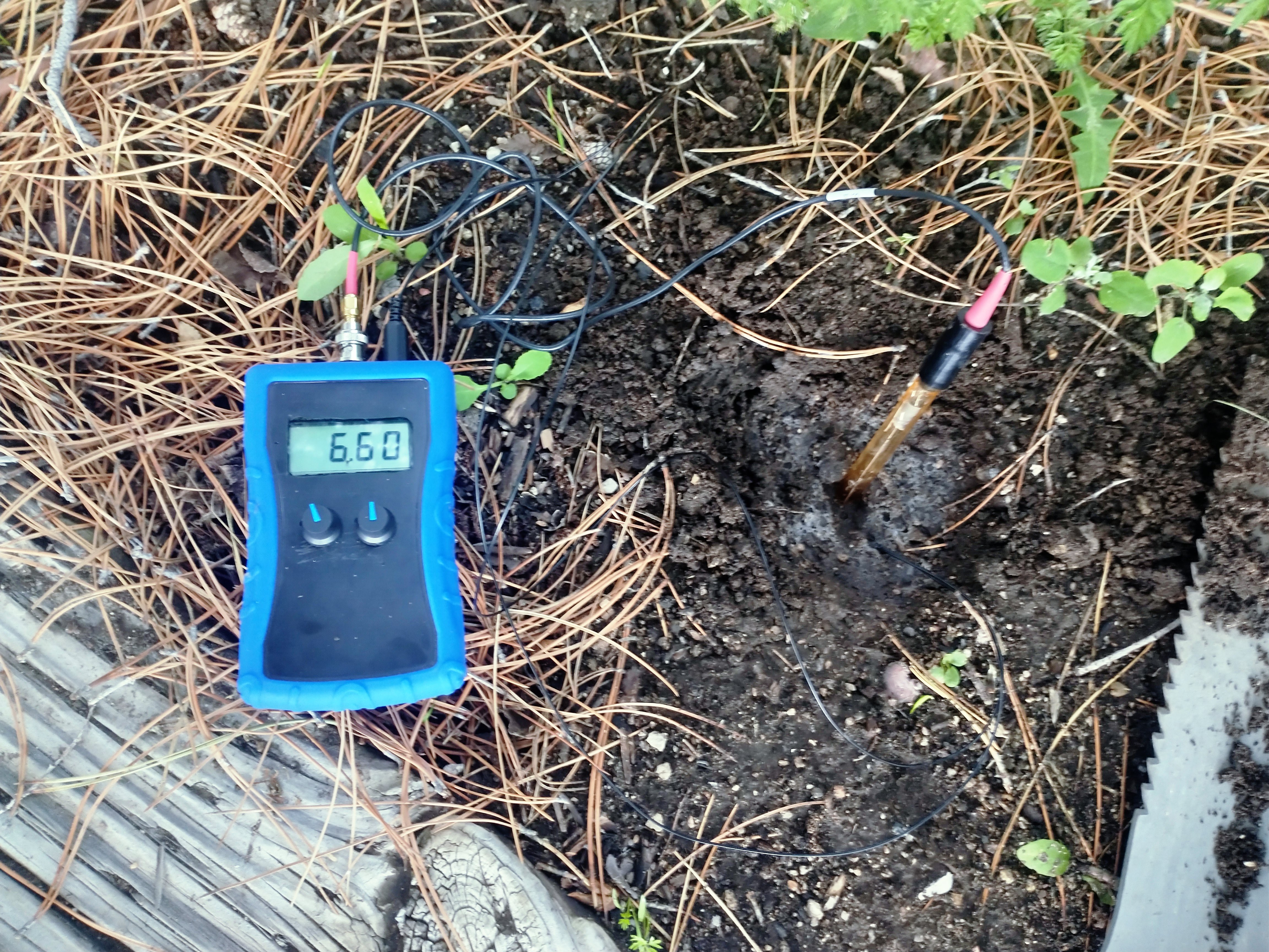
The circuit is promising, even usable for home/garden use as-is (I suspect it is quite accurate if measuring on the same side of 7.00 that it is calibrated at -- that is, measuring acids when the 2nd calibration point was an acid). And I did use it to measure my garden bed directly below a pine tree: 6.6, well within the range most vegetables need to effective use soil.
But there is obviously much room for improvement in accuracy across the scale and unfortunately I won't have time before the end of the challenge to investigate. I have a few ideas to begin with when I have time:
- I am running the ICL7106 from the 7805 voltage regulator, so it is getting only +/- 2.5V rails... could the integrator be saturating on the negative input? I could run the ICL7106 directly from the 9V battery and the LMV358A from the 5V supply to test this.
- Leakage currents? Since the error seems to occur when the input voltage is positive (acidic solution) I wonder if there is leakage somewhere causing a voltage to develop through the large output impedance of the pH probe. I have a guard ring around the op-amp input on one side of the PCB, but I have not otherwise been very careful with power routing or cleaning flux off of the PCB after all of the rework required to fix mistakes on the prototype PCB.
- Could the lmv358a offsets be dependent on the polarity of the input enough to cause an offset? I will try to find an actual precision op-amp I can drop in place to see how that affects the accuracy.
Mistakes
Many mistakes were made both in the schematic and even more in the PCB in my rush to get this project working by the challenge deadline. All of these have been fixed in the current project files on Github.
- I drew the footprint for the LCD with one side of pins numbered backwards (pins 21-40 were reversed)! I didn't discover this until I had assembled the board, powered it on, and got a scrambled display. I clipped all the legs (pins 21-40), bent them away from the PCB, and used a wire wrap tool to bodge them all to their correct routes.
- I also drew the LCD footprint too narrow (it was not clear from the technical drawing I was working from that the pins go out 1.27mm from the body on each side). Luckily this was close enough that the pins could easily be bent to fit.
- The lmv358a op-amp has a maximum operating voltage of 5.5V, but in the prototype I had it powered directly from the 9V battery! Luckily I noticed this before powering on the board and was able to bodge in a 7805 linear regulator to power the whole board from.
- I also forgot the decoupling capacitors for the lmv358a. I bodged these in as well.
- I had R6 and R7 swapped, so the offset voltage was 0.3V instead of 0.7V. I was able to unsolder, swap, and resolder those.
Future improvements
Other than improving the accuracy found in my initial testing of the prototype, I have made these improvements to the schematic (available in Github) so they will be part of the next revision boards:
- The zero adjustment is too sensitive. It uses the 0.6V across D1 which was a silicone diode in the prototype. I've changed that to a Schottky diode (SS14) which should halve the voltage range of the offset.
- Even more important than the op-amp decoupling caps turned out to be decoupling the wipers of the 10K potentiometers which were picking up noise from the 7106 oscillator. After adding 100nF from the wiper to -VDC the display became much more stable.
- I forgot a power switch and had to turn the prototype on and off by removing and inserting the battery. The current board files have a connector for a switch on the PCB, though I'm not sure where to mount it yet... if I can find a small rocker switch I'd like it to go next to the BNC jack.