 Ruud van Falier
Update 30 Sept 2023: Added more instructions that allow you to enable COLOR schemes!
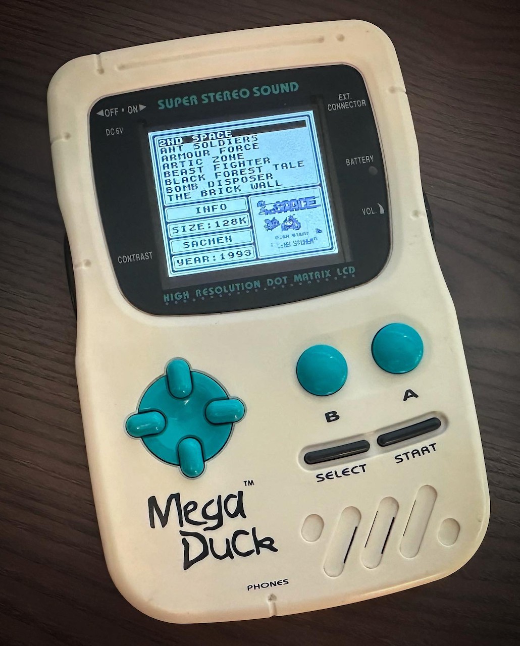
The Mega Duck (also known as CougarBoy in some regions) is an obscure handheld game console that was marketed as a competitor to the Game Boy.
Both systems have lot of technical similarities but they are not compatible.
The dot matrix LCD screen on the Mega Duck is very similar to the one in the Game Boy and it is horrible to look at. Pixels are very hard to see, especially when object are moving (which is always the case during gameplay).
I had not touched a Mega Duck for well over 25 years when I recently obtained one.
Having one in my hands again gave me a nostalgic feeling, but when I tried to play on it I could not imagine that I used to spend countless hours as a kid looking at this blur of a screen.
That's when I thought about the IPS screen modifications that are available for the Game Boy; would that work for a Mega Duck too?
After doing some research, I came to the conclusion that the dot matrix LCD used in both the Mega Duck and the Game Boy have exactly the same technical specifications.
So I ordered an IPS screen mod for the Game Boy (https://www.retromodding.com/products/game-boy-ips-lcd-rips-v5) and came up with a gameplan:
- Use my oscilloscope to determine the pinout of the Mega Duck and Game Boy LCD connector.
- Try to connect a stock Game Boy LCD screen to my Mega Duck.
- If that works, then connect the Game Boy IPS mod to the Mega Duck.
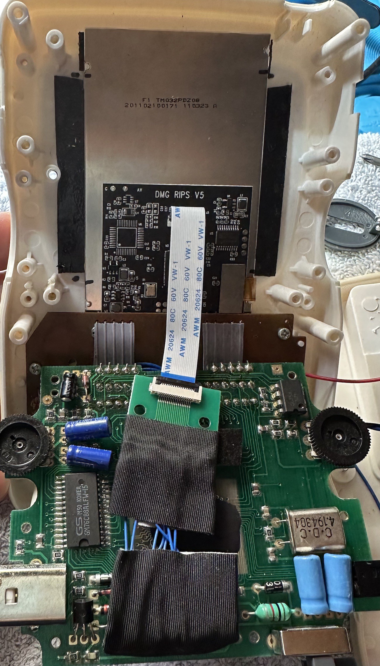
- The Game Boy IPS mod has an additional large PCB that replaces the control PCB when modding a Game Boy which we don't need in the Mega Duck.
Next step is to remove this PCB and hook up the Mega Duck motherboard directly to the IPS board, without the controller PCB in between. - Wrap it all up.
Finding the pinouts and mappings
Before going into the pinout description and mapping, let's first layout the connectors so we know what is pin 1.
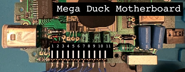
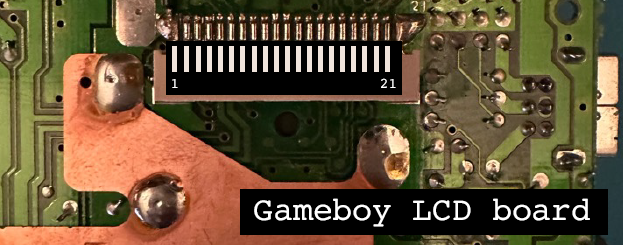
Next up, figuring out the pinout.
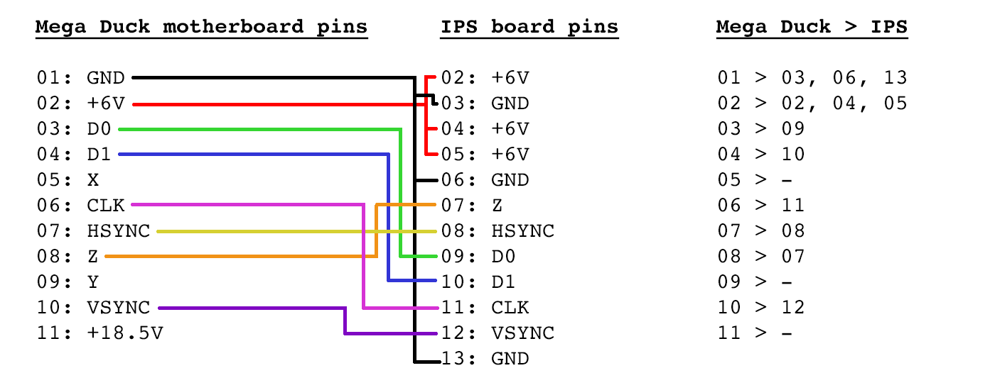
Here is how the Mega Duck motherboard LCD connector maps to the Game Boy LCD board connector.
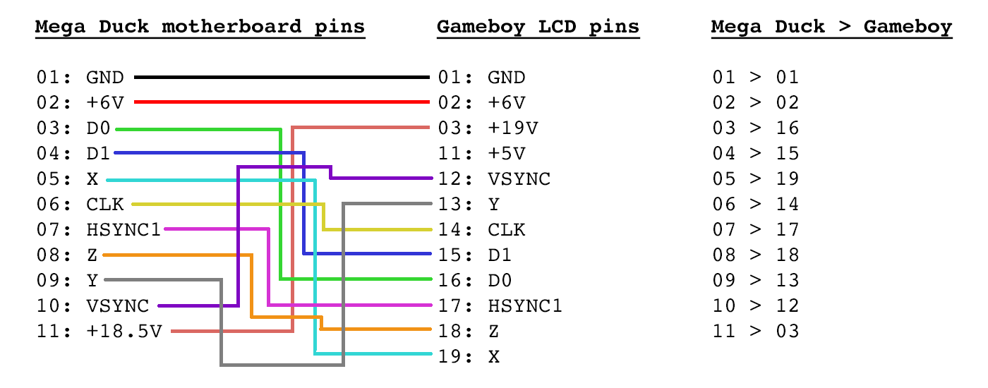
There are a couple of pins which have an unknown function and I didn't bother to spend more time figuring out what exactly it is they do because I do not need to know: I simply try to match signals between the boards so I can map the pins from one board to another. What the pins do exactly is less relevant.
Based on some Game Boy schematics floating around online, signal X may be "alt signal", signal Y may be "control" and Z may be "data latch". Signal Z is almost in sync with HSYNC, so they seem related (I initially marked them as HSYNC1 and HSYNC2).
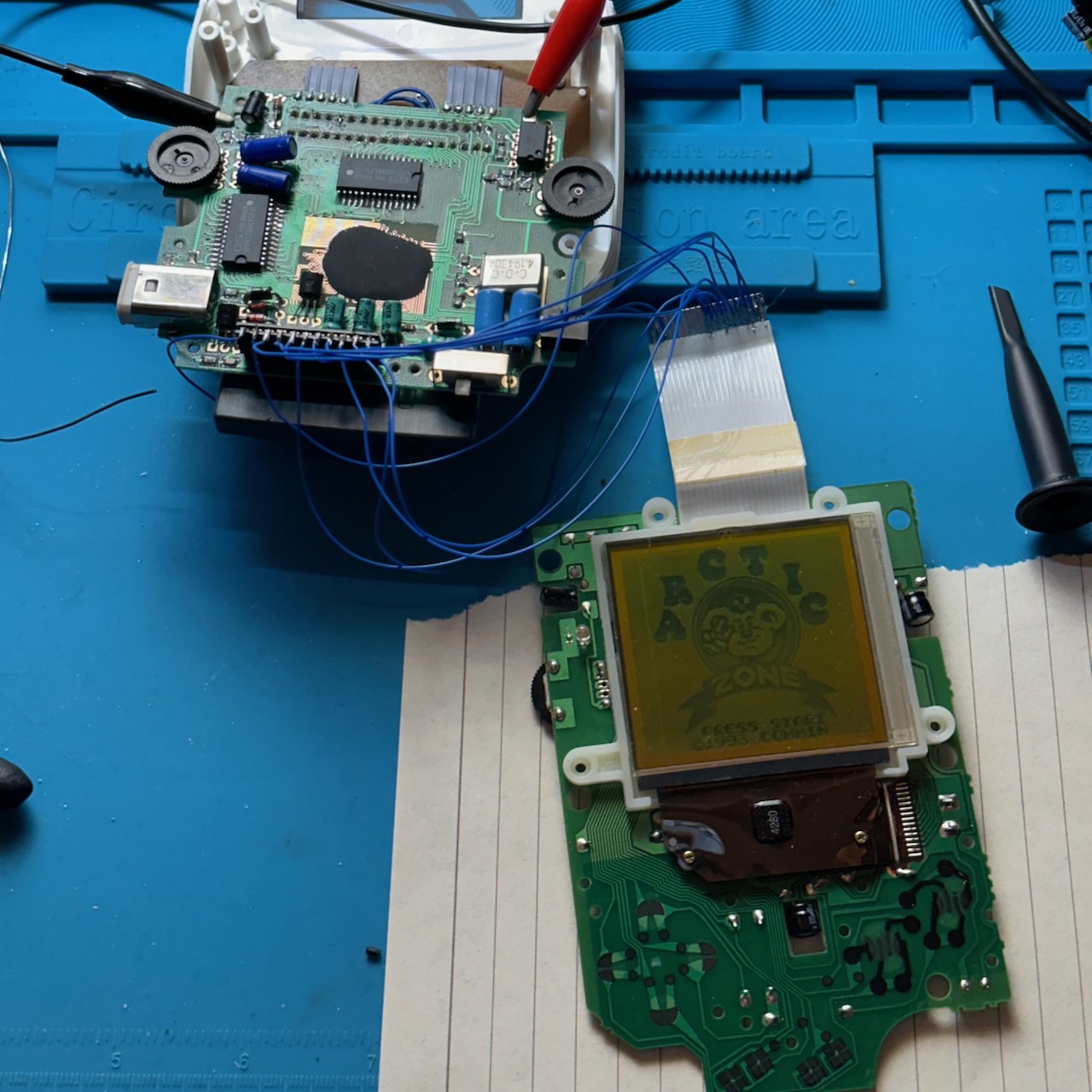
Connecting the stock Game Boy LCD to the Mega Duck
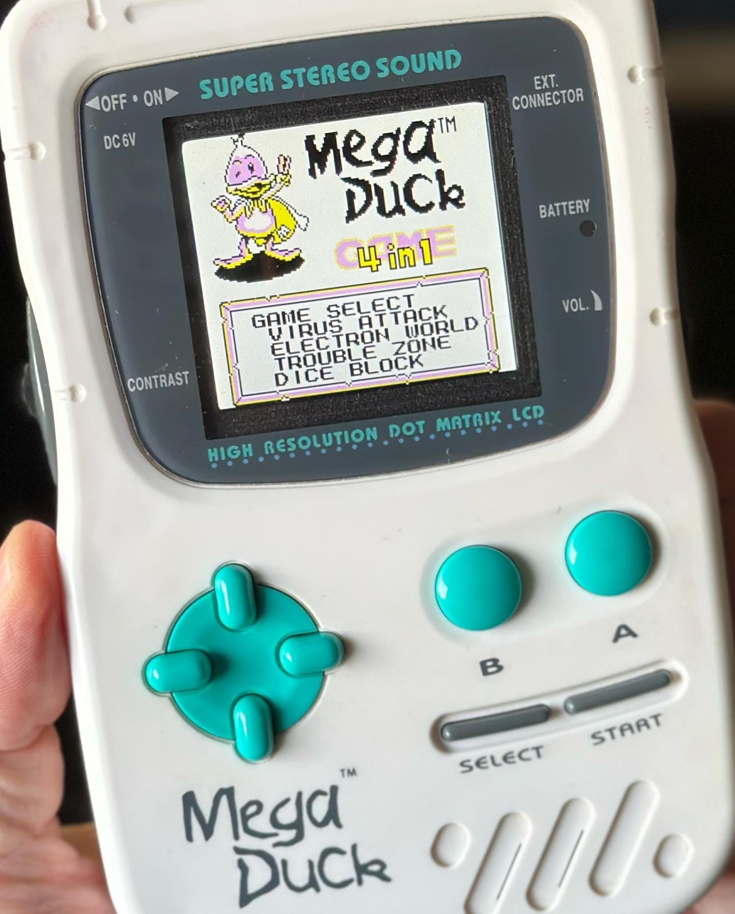
Now that I figured out the mapping, I was able to succesfully connect the stock Game Boy LCD to the Mega Duck.
And with that knowledge it was easy to replace the stock LCD with the IPS screen mod.
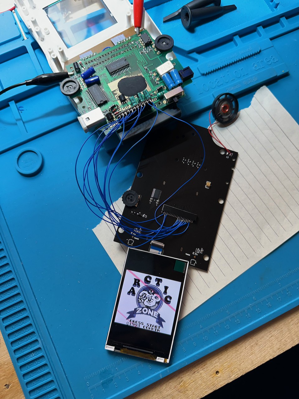
Eliminating the controller PCB
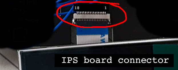
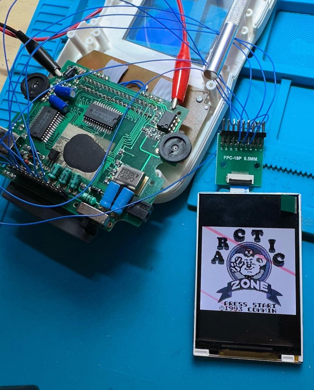
In order to eliminate the controller PCB, I first needed an adapter board because it is impossible to solder to the 0.5mm pitch leads of the IPS board connector. I got this one: https://aliexpress.com/item/1005001781167693.html (choose the 0.5mm to 2.45mm and 18 pin)
Based on my oscilloscope findings, this is the pinout and mapping for the IPS board controller.
With the adapter board it was easy to hook up the IPS directly to the Mega Duck motherboard.
Wrapping up
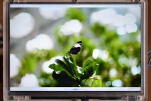
Now, to wrap it all up I cleaned up the wiring, wrapped the connectors in some tape to keep it all in place and attached the IPS screen inside the Mega Duck case using double sided tape (note that I removed one screw post to make it fit).
Aaaaand it's done:
To conclude, here is a video of the result:
UPDATE: The RIPS v5 mod supports color schemes and a control menu.
I have added instructions below on how to change the Mega Duck mod so you can enable this:
Step 1: Obtain the rotary encoder wheel
In order to control the screen colors and the menu, you need a rotary encoder...
Read more »

 tshen2
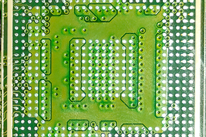
 Mortimer
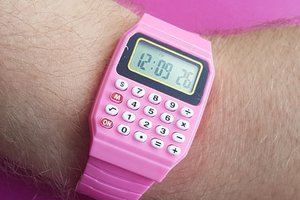
 davedarko
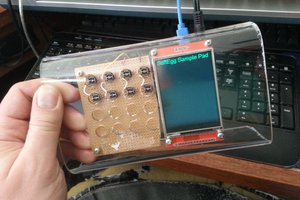
 T. B. Trzepacz
wow this is wonderful, thank you very much for the tutorial, I'm going to try it with one that I've had for many years.