I changed the main coil from 32mm to 60mm. Same induction value. Tested, working as expected. Yeay! Now I want to make bigger secondary coil, instead of quarter wave. Hopefully get more power.
Let's see how much more voltage we get once we have more turns.
It's interesting and not what I've expected.
If I use coil with wire length of 1/4 wave length I got 660v (and clean sine wave) on the other hand using longer wire of 3/4 wave length gets only 520v and distorted signal.
I'll try to make a list of wire length (in wave length) vs max voltage across the coil:
1/4: 660v
1/2: 460v
What?! It doesn't make sense, bigger coil is more voltage at least it how it works in transformers.
So, I've tried different approach. Connected coil to 1khz pulses and was looking for oscillation but got oscillation of about 500khz not what I have expected.
Clueless again...
[Two hours later]
New tactic, let's try to create frequency sweep using Arduino and AD9833 frequency generator. I will try amplify the signal using A-class 2n2222 transistor. Check the output of coil to determine if we hit self resonance frequency. If this will not work I will be totally clueless... like totally clueless...
This is the digital part that can change frequency from 0 to 12MHz (based on AD9833)
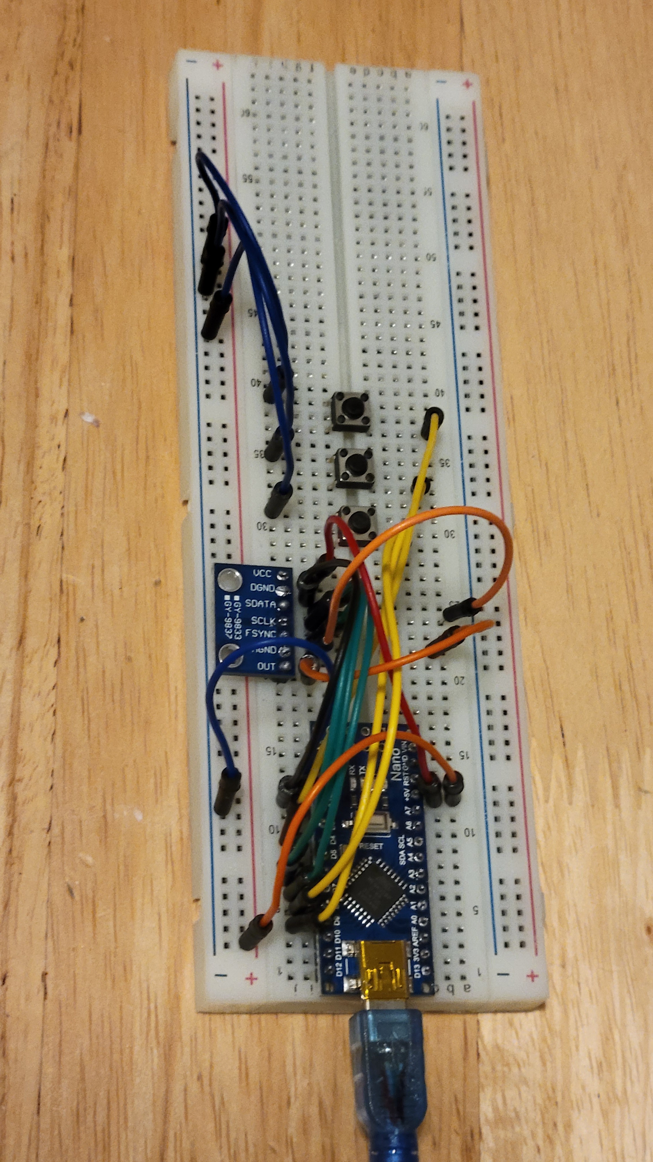
Now I should add 2n2222 transistor to drive a coil with 600mA instead of few mA.
The best way is to start with simulation. LTSPICE solution
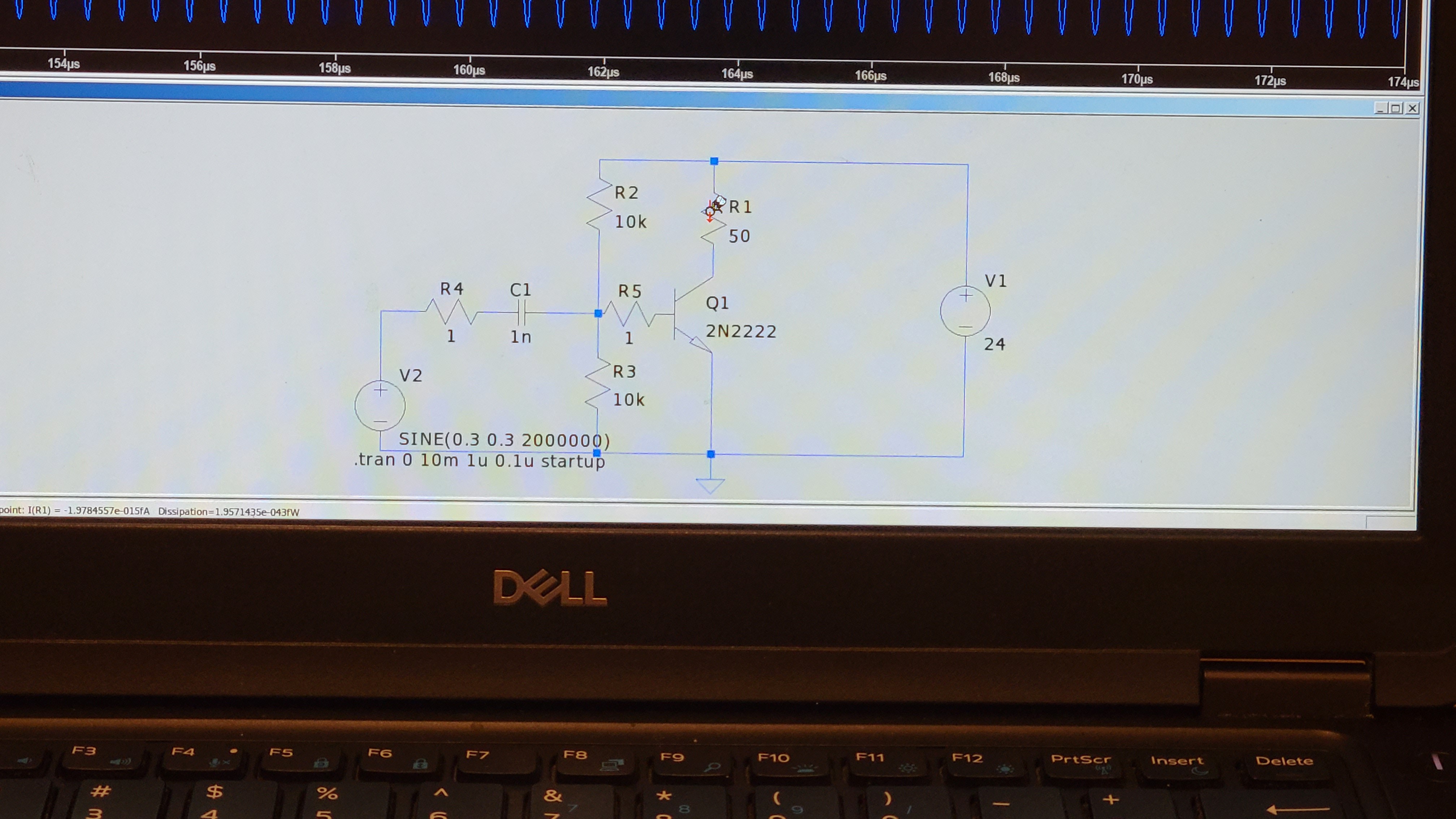
Which gives, although simulated, 4v to 22v swing and gives 400mA max. Which is far enough from 500mA rms and powerful enough to drive a coil.
I've noticed that 50ohm resistor can get lots of power since there is almost 0.5v Vpp.
So, which power rating for resistor should I use? Well converting 0.5Vpp gives about 0.14v rms and by I^2R = P we get about 1Watt.
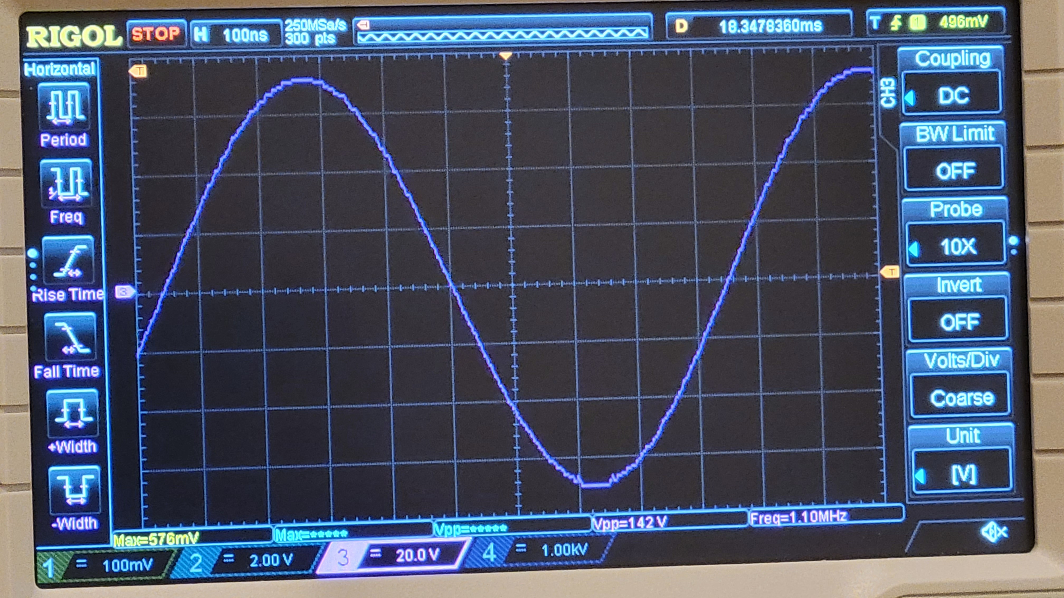
Ok, made the circuit
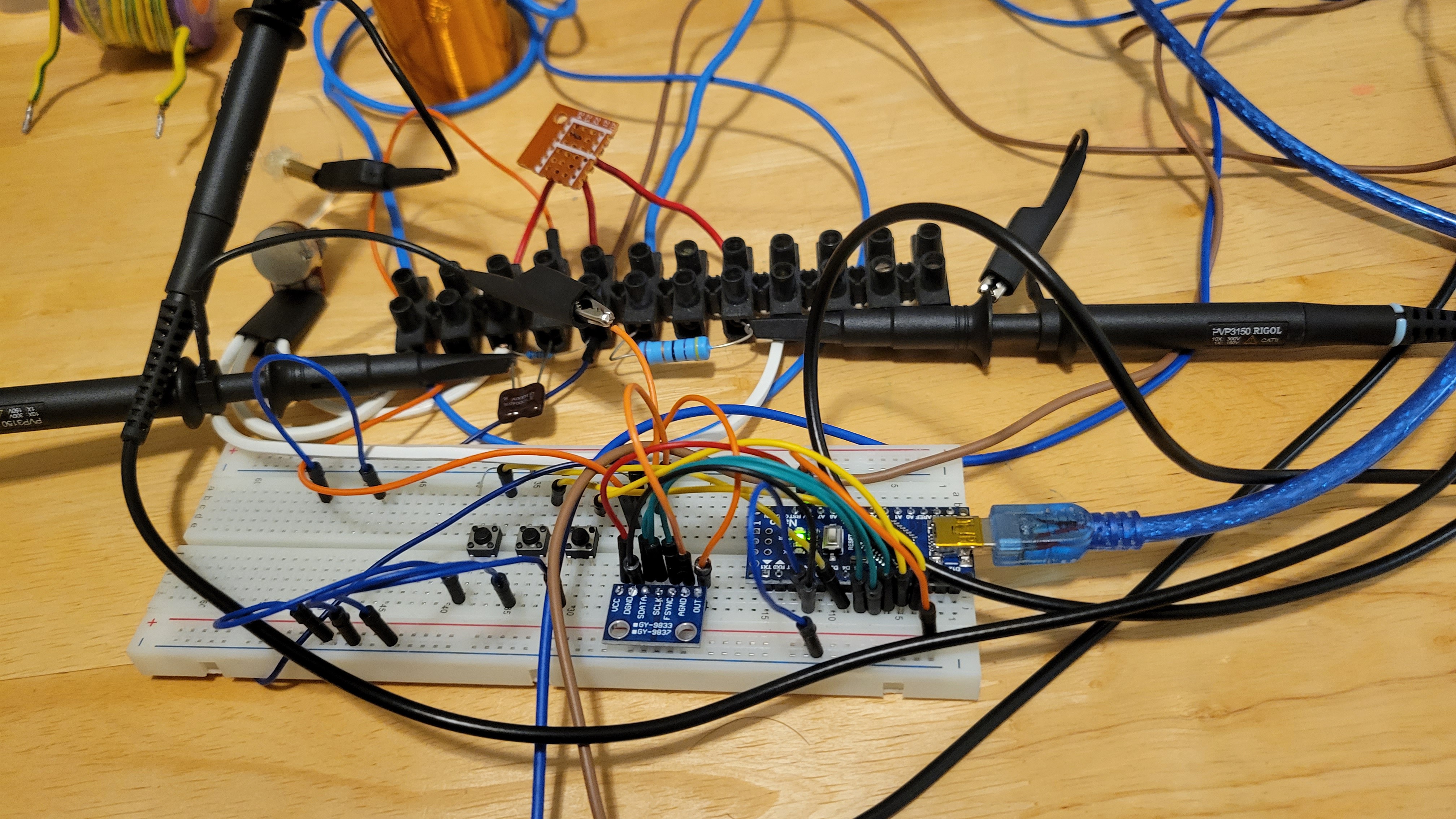
It's very ugly since all high current is not on a breadboard. It's far from 22v swing actually only 2v. But once it gets the right frequency the coil got unbelievable 14.2v.
Now we can craft coil with self resonance of 10MHz.
Using AD9833 was a mistake, first it cannot go beyond 12MHz. Second, it's output is low and varies greatly over different frequencies.
So I've changed it to Si5351 although it's only square signal generator the output from 2n2222 was 17-24Vpp. This powerful signal generator helped me to distinguish between noise and real self resonance.
Solved that, now new problem arised. Since coil self capacitance is about 1.5pF, the capacitance of the probes changing the frequency. I guess I should use well known capacitor to find coil's inductance from resonance frequency. Once I have this I will assume 1.5pF and try to figure out which coil is should make so it's self resonance frequency is 10.4MHz
I've started from cylinder diameter D=3cm wire diameter 0.3mm and wrapped about 90turns which gave me coil height of 3cm. From there I started to remove turn by turn to find the self resonance frequency. At 2.8cm coil height I started to see discharge (plasma) but it also done some strange noise from the coil. Removing more turns at 2.6cm coil height I got maximal discharged and I could start it without touching it with a metallic object.(Which is nice since I don't want to start it by touching it, it's much better to ignite it by changing the voltage) plus the current consumption from power supply dropped from 1.2A to 0.2A. Removing more coil turns I got to 2.4cm height of coil the discharge become weaker and chirping noise returned. Down from there it couldn't produce any discharge.
So, I couldn't find the exact frequency but coil with 80 turns gave some nice discharge. The 15MHz coil uses secondary coil of 0.36mm instead of 0.3 I've used. From my experience with main coil any resistance can kill oscillation that's why I suspect that it's resistance issue.
Next step will by try to do the same experiment with 0.6mm wire diameter.
Tried 0.6 still didn't find the correct frequency. I have tried different coil simulators like JavaTC amd coil64. All of them gives different answers but none if them getting me to the right coil dimensions.
Frustrated again, until I found this https://www.easternvoltageresearch.com/tesla-coil-workshop/measuring-the-resonant-frequency-of-your-secondary-coil/
I stuck me like a lightning. I was trying to check voltage over the coil. The problem was that it capacitance was changed due to probe capacitance of 15pF. The method presented here is much better.
After frying few 2n2222 transistors I've ended up with only arduino controller and Si5351. Actually it was best setup yet. I could clearly see the highest point but was hard to find the lowest point. As desicribed in https://wiki.analog.com/university/labs/comms_lab_isr_adalm2000 I should look for the lowest point.
My schematic is simply:
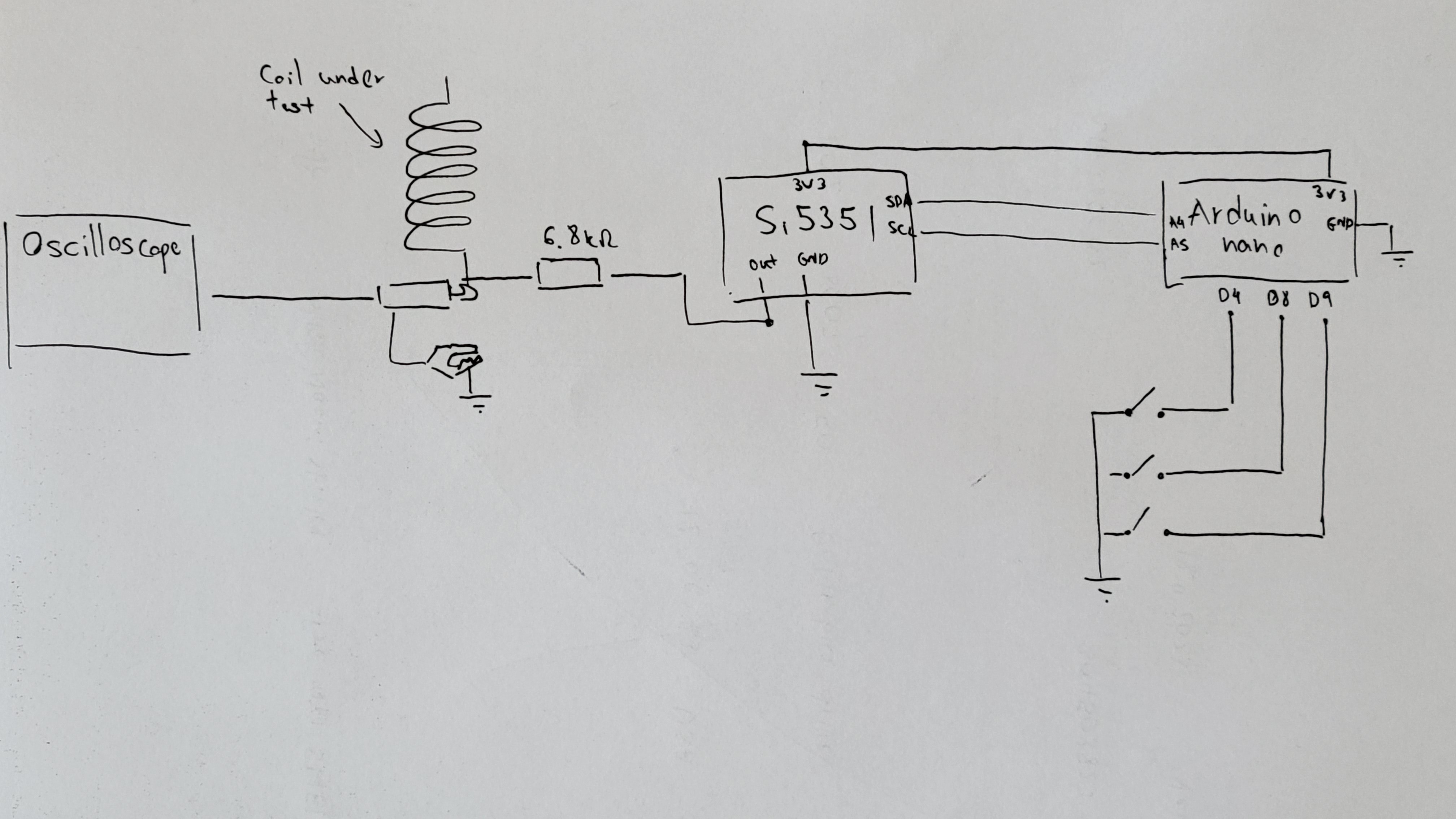 Using this technique I found the main frequency. Once I got it connected to Tesla coil main coil, I've reduced the frequency even farther by stretching the wire up. After careful changes and of 1/8 circle of main coil. I found best configuration.
"But I still didn't find what I was looking for "
I am able to find the frequency with minimal reactance. But yet I don't get full power.
I got an idea, we made 1/4 wave resonater amd we made a coil with 10.9Mhz lowest reactt. Whatif we combin them together. We will make a one coil with length of wire of 6.8m AND self resonance of 10.9MHz. For example coil with 4.7cm diameter and 0.6mm wire diameter, 45 turns. It should be 3cm of coil height.
Did it, didn't work... arrr!
Opened the coil it was actually 7.03m instead of 6.8m, anyway it did gave bigger flame/spikes but was not too powerful.
Clueless again, arrr!!!
Actually finding the minimum with Si5351 is tricky. Maybe it was not the minimum where I think it is? I think I need different approach to this problem.
Bought simple signal generator and counter. The frequency is 10.87
Made the coil to be tuned to that exact frequency. Felt lucky and burned MOSFET. Tried different approach and fried another one DAMN! It was my last IRFP260n. Project halt until get a bunch of new one(hopefully not fake)
Now, after I fried my last MOSFET, I found some nice articles about quarter wave coils amd even online calculator. My assumption was that speed of light in coil is constant in coil and equal speed of light in vacuum was wrong. So calculations of length was wrong too.
https://gorchilin.com/calculator/coil14?lang=en
And in my case
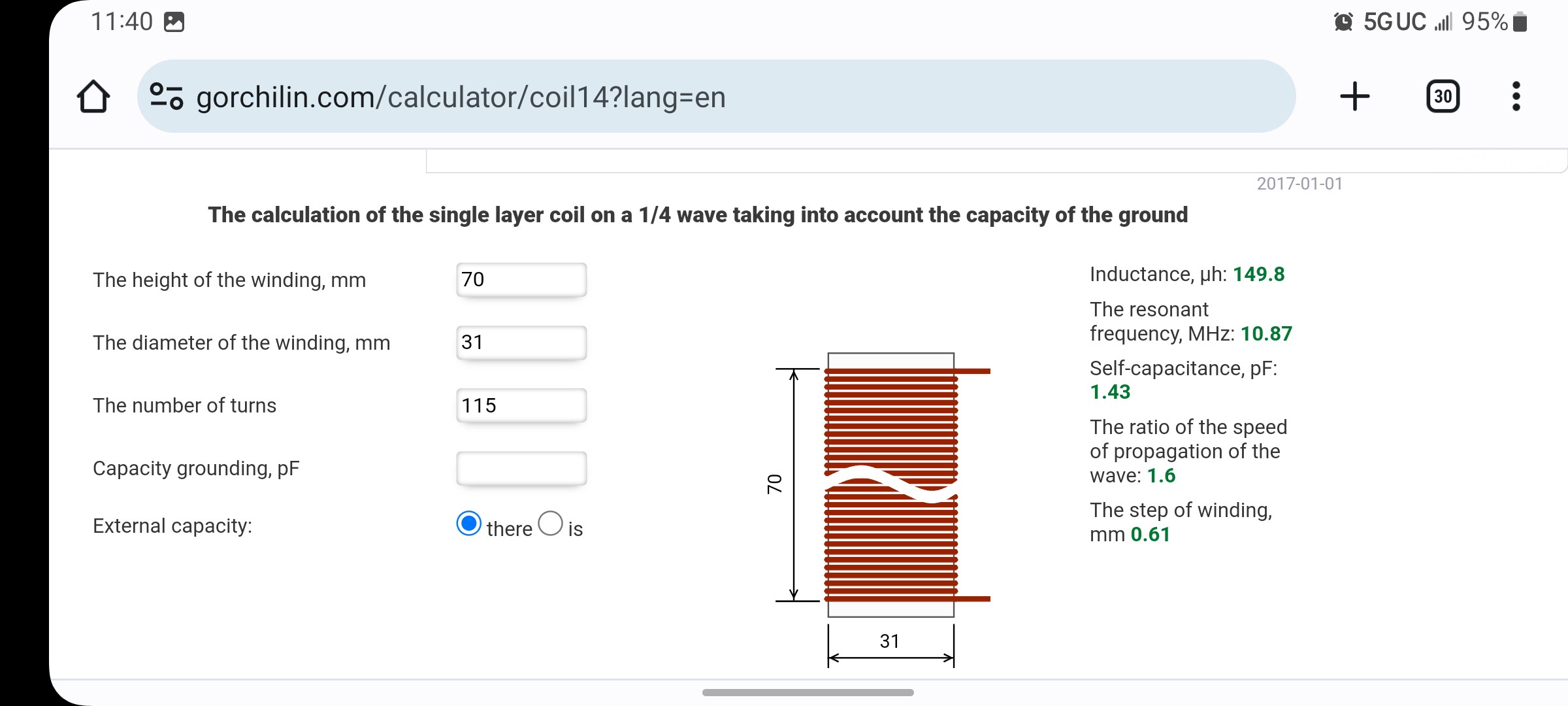
Which is almost double the length I have used.
Nice explanation about quarter wave and standing waves: https://www.allaboutcircuits.com/textbook/alternating-current/chpt-14/standing-waves-and-resonance/
Now let's wait patiently to components to arrive.
Still waiting for components to come, meanwhile I made a coil with 10.8MHz resonance frequency.
The old one turned out to be 11.9 Mhz
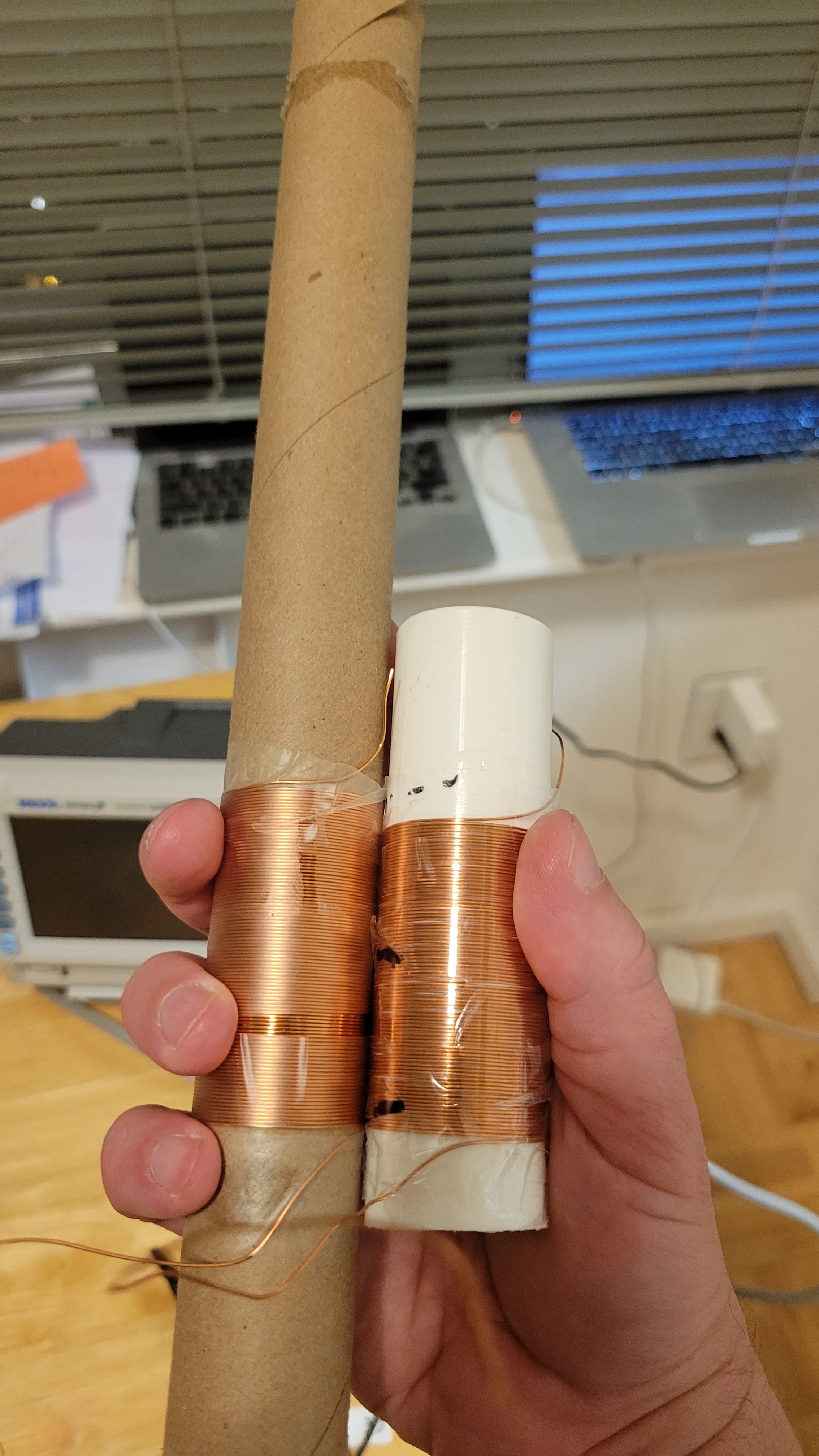
Such a minor difference gives huge difference of almost 1MHz
One important insight, the voltage near top of the coil is proportional to voltage at bottom. I didn't find any frequency that voltage goes down in the bottom and up in the top of coil.
Discussions
Become a Hackaday.io Member
Create an account to leave a comment. Already have an account? Log In.