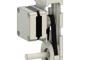
The Smart Knob is based on ESP WROOM 32E microprocessor module. The haptic feedback is realized by burying a BLDC motor in the main body of the knob. A magnetic sensor senses the direction of the knob and sends the angle to ESP32. ESP32 controls the luminance of an LED based on the direction of the knob. On the top of the knob is an LCD screen showing the direction. A website serves as the user interface. Users can change the mode of the knob or calibrate it from the website. A web server is running on the local host or AWS. The server transmits data to ESP32 and the website through websocket. The block diagram of the system is shown below.
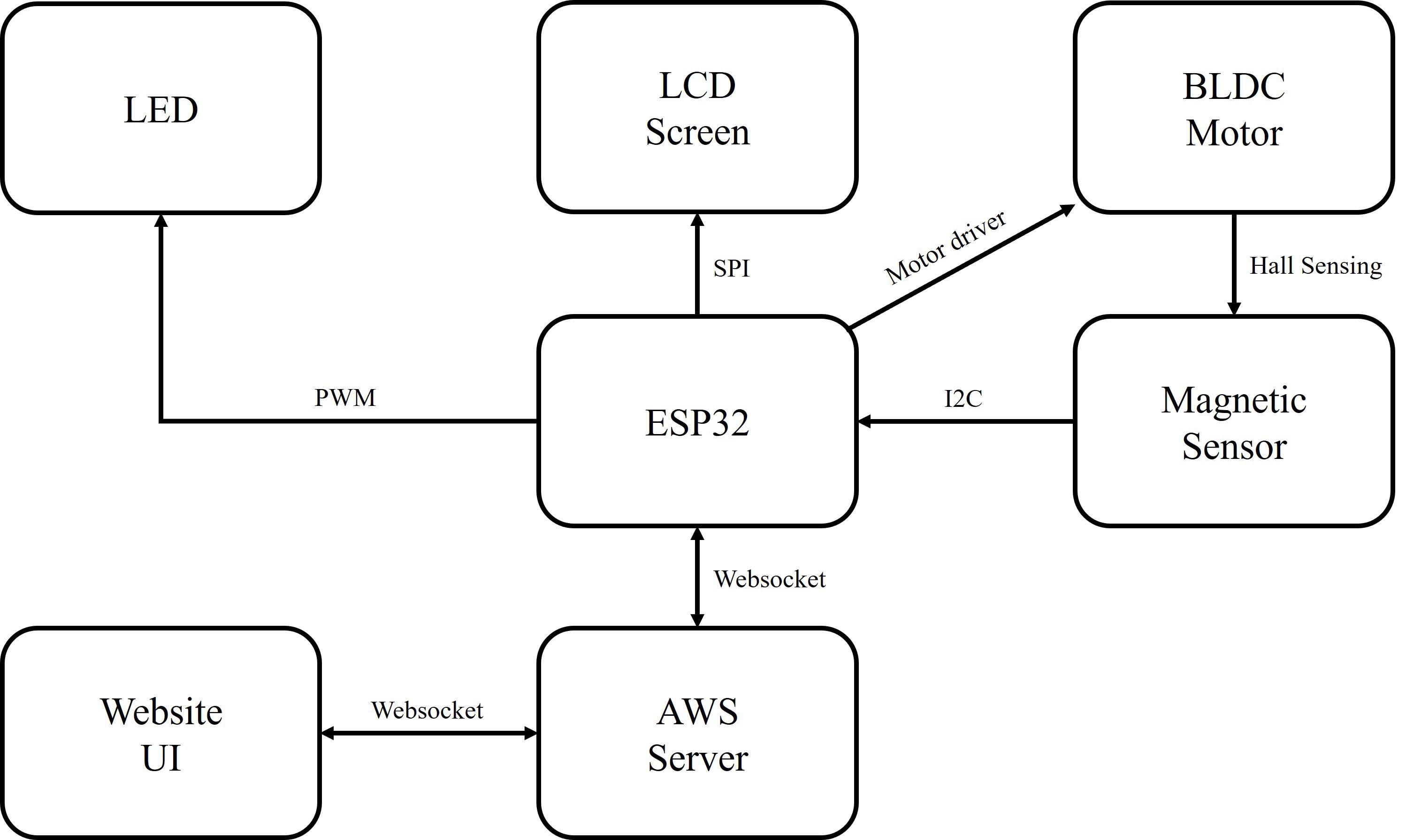
Figure 1. Block Diagram
Algorithms and Code
1. Magnetic Sensor
We use Infineon TLV493D as the magnetic sensor. During setup, the ESP32 sets up I2C communication with the sensor by configuring the two wire interface and device address of the slave chip. In the main loop, the ESP32 requests data from the chip when needed. It is worth noting that TLV493D doesn’t have a register for the angle of the magnetic field but only has registers for the x and y axes. So we need to use the TLV493D library function to get the updated magnetic flux densities along the x and y axes and add a new function getSensorAngle() under class TlvSensor, as shown below:

Figure 2. Obtain the Sensor Angle
2. BLDC Motor
We use the SimpleFOC library to control the BLDC motor. The library configures the control type of the motor and generates PWM signals for the motor driver based on controlling parameters. For example, under the non-haptic mode, we set the control type to MotionControlType::torque and set the controlling parameter to 0:
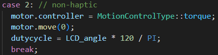
Figure 3. Motor FOC
3. LCD Screen
ESP32 sets up SPI communication with the LCD screen and plots a new frame every time the magnetic field angle is updated:

Figure 4. LCD Screen Plot
4. LED
ESP32 generates PWM to modulate the luminance of the LED. During setup, we pick one of the 16 PWM channels of ESP32 and configure the PWM frequency and resolution. In the main loop, the PWM duty cycle depends on the current mode and position of the knob.
5. Modes
The knob has three modes: haptic, non-haptic and calibration. The mode is determined by a variable on the webpage.
Under the haptic mode, the knob has seven slots and can provide haptic feedback at each slot. And the LED has seven different levels of luminance.
Figure 5. Haptic Mode
Under the non-haptic mode, the knob moves in a seamless rotational motion, and the brightness of the LED also changes smoothly.

Figure 6. Non-haptic Mode
When calibrating, the knob automatically moves to the zero position, where the angle of the magnetic field is equal to zero.

Figure 7. Calibration Mode
6. Server and Website
The server is written in Python Tornado. It has two websocket endpoints for the website and ESP32 separately.
In the C++ main loop, the ESP32 will send requests to the server through websocket, together with the value of calib_done, which indicates whether the calibration process is finished. Under the ESP32 websocket handler, the server receives the value of calib_done and updates the value to the website client. The website sends back the value of mode, which determines the mode of the knob. Next time the ESP32 sends a request, the server will also send back the value of mode to ESP32.

Figure 8. Website Handler

Figure 9. ESP32 Handler
PCBs
We built a set of PCBs for every step including prototype, testing and final product. They are built in EaglePCB and KiCad 7.
For the prototype, we built a simplified motor base, mainly for setting our BLDC motor with 3 tiny screws, and placing the magnetic encoder right beneath the center of the motor. The encoder needs to be extremely precise since the motor itself is not much bigger, a millimeter’s deviation will cause serious troubles. So, we placed it in 0,0 in both axes and...
Read more »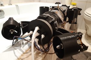
 Noeël Moeskops
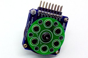
 bobricius
 Dev Joshi