The Smart Knob is based on ESP WROOM 32E microprocessor module. The haptic feedback is realized by burying a BLDC motor in the main body of the knob. A magnetic sensor senses the direction of the knob and sends the angle to ESP32. ESP32 controls the luminance of an LED based on the direction of the knob. On the top of the knob is an LCD screen showing the direction. A website serves as the user interface. Users can change the mode of the knob or calibrate it from the website. A web server is running on the local host or AWS. The server transmits data to ESP32 and the website through websocket. The block diagram of the system is shown below.
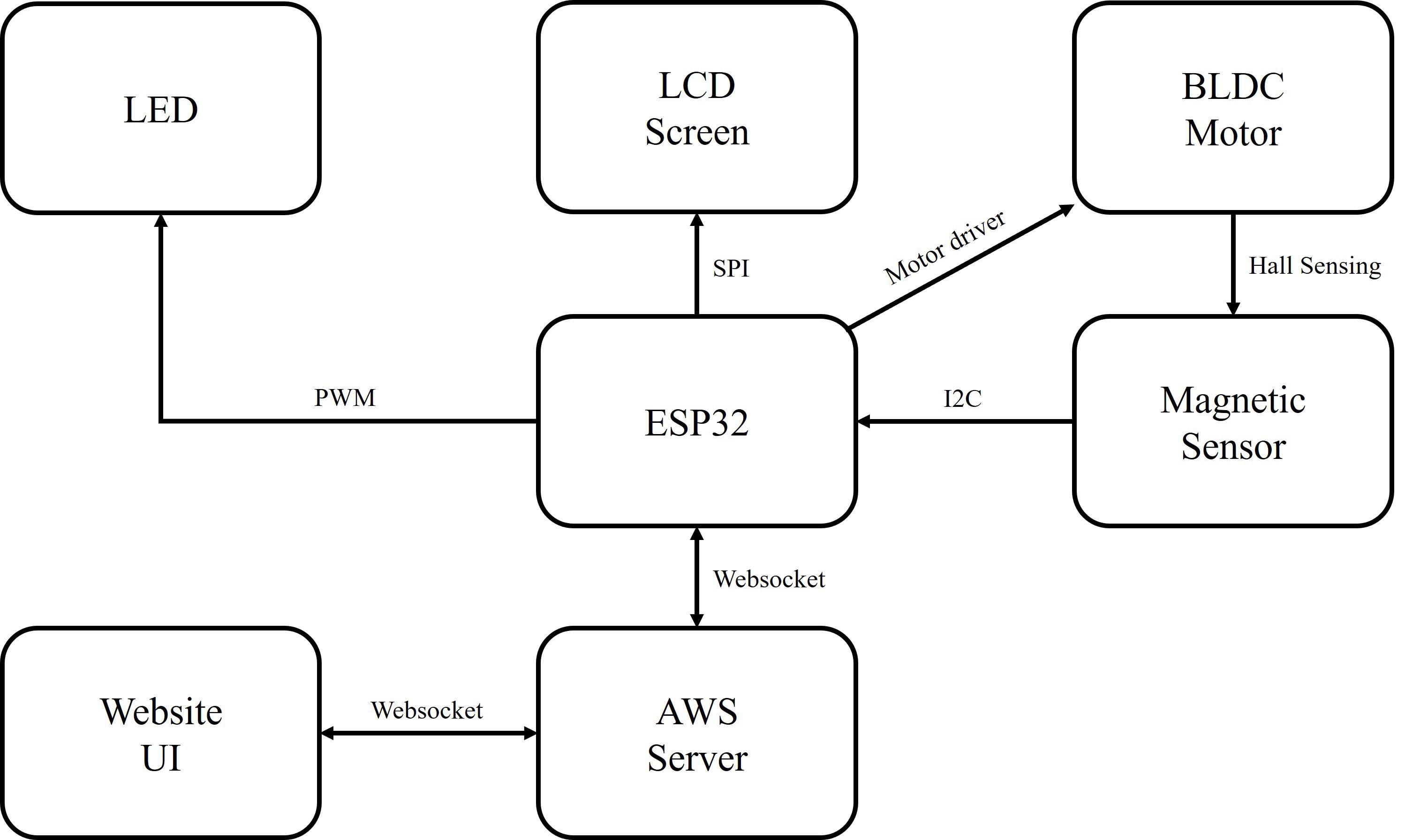
Figure 1. Block Diagram
Algorithms and Code
1. Magnetic Sensor
We use Infineon TLV493D as the magnetic sensor. During setup, the ESP32 sets up I2C communication with the sensor by configuring the two wire interface and device address of the slave chip. In the main loop, the ESP32 requests data from the chip when needed. It is worth noting that TLV493D doesn’t have a register for the angle of the magnetic field but only has registers for the x and y axes. So we need to use the TLV493D library function to get the updated magnetic flux densities along the x and y axes and add a new function getSensorAngle() under class TlvSensor, as shown below:

Figure 2. Obtain the Sensor Angle
2. BLDC Motor
We use the SimpleFOC library to control the BLDC motor. The library configures the control type of the motor and generates PWM signals for the motor driver based on controlling parameters. For example, under the non-haptic mode, we set the control type to MotionControlType::torque and set the controlling parameter to 0:
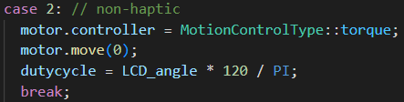
Figure 3. Motor FOC
3. LCD Screen
ESP32 sets up SPI communication with the LCD screen and plots a new frame every time the magnetic field angle is updated:

Figure 4. LCD Screen Plot
4. LED
ESP32 generates PWM to modulate the luminance of the LED. During setup, we pick one of the 16 PWM channels of ESP32 and configure the PWM frequency and resolution. In the main loop, the PWM duty cycle depends on the current mode and position of the knob.
5. Modes
The knob has three modes: haptic, non-haptic and calibration. The mode is determined by a variable on the webpage.
Under the haptic mode, the knob has seven slots and can provide haptic feedback at each slot. And the LED has seven different levels of luminance.
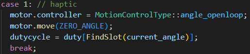
Figure 5. Haptic Mode
Under the non-haptic mode, the knob moves in a seamless rotational motion, and the brightness of the LED also changes smoothly.

Figure 6. Non-haptic Mode
When calibrating, the knob automatically moves to the zero position, where the angle of the magnetic field is equal to zero.

Figure 7. Calibration Mode
6. Server and Website
The server is written in Python Tornado. It has two websocket endpoints for the website and ESP32 separately.
In the C++ main loop, the ESP32 will send requests to the server through websocket, together with the value of calib_done, which indicates whether the calibration process is finished. Under the ESP32 websocket handler, the server receives the value of calib_done and updates the value to the website client. The website sends back the value of mode, which determines the mode of the knob. Next time the ESP32 sends a request, the server will also send back the value of mode to ESP32.

Figure 8. Website Handler

Figure 9. ESP32 Handler
PCBs
We built a set of PCBs for every step including prototype, testing and final product. They are built in EaglePCB and KiCad 7.
For the prototype, we built a simplified motor base, mainly for setting our BLDC motor with 3 tiny screws, and placing the magnetic encoder right beneath the center of the motor. The encoder needs to be extremely precise since the motor itself is not much bigger, a millimeter’s deviation will cause serious troubles. So, we placed it in 0,0 in both axes and built the rest of the components over it. Basically, it just contains a magnetic encoder, a BLDC motor driver, a jack for connecting the motor, and some pads and pins for validation and debugging, since all other stuffs like ESP32 are on other breakouts and breadboards (we used our ESP32 breakout from EE326). This is a screenshot of our prototype base board.

Figure 10. PCB for Prototype Base Board
After validating and testing our first thought and a few revisions, we started to build our final board. This board has been through many revisions, we gradually reduced some of the components we planned at first, such as the ambient light sensor for adjusting the screen’s brightness automatically, and piezoresistors for recognizing the move of pressing the knob in order to choose a different function and mode, which we are able to realize on the web server remotely, and also, we changed our chip to the one we had used in EE326, ESP32-WROOM-32E, instead of the original one, ESP32-PICO-V3 which is more advanced and more compact. This is mainly because we want to make some changes to the chip and make it more challenging for routing because the WROOM-32E is much bigger, as figure 11 shown below.
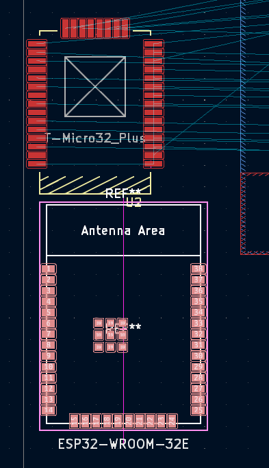
Figure 11. Compare between WROOM-32E (lower) and PICO-V3 (upper)


Figure 12. (a) Final PCB Base Board, (b) Final PCB Base Board with Copper
Figure 12 above shows the final PCB with all components integrated; copper layers are removed in 12(a) to provide a clearer sight of the components.
We used KiCad 7, a free and powerful open-source CAD tool to draw the schematic and PCB. It is quite different from EaglePCB we learnt in EE326, but we conquered it and made out the Gerber files for manufacture. Of course, the factory pointed out some faults that may lead to faulty manufacture and we revised it, after a week, the board came across the sea to us.
When soldering, we faced a lot of problems. They are not that big but they are good lessons to learn from in our progress. We did not buy the exact resistors and capacitors we need, and this could be bad for reducing the robustness and reliability of the whole system.
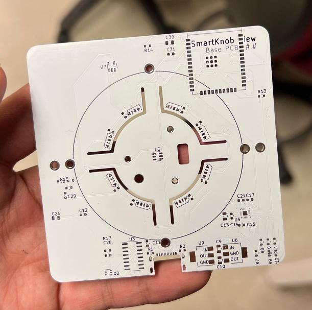

Figure 13. (a) Final PCB Base Board Front View, (b) Final PCB Back View
By the time this report is written, we have just finished soldering our final PCBs, but the ESP32 on our base board cannot be programmed even with a ‘waiting for download’ message. But we are writing a testing procedure in the middle of the quarter using a prototype, which is functionally the same as the final PCB, only easier to debug and design.
Also, we have a fatal mistake made by the PCBWay that the board for the screen has not been drilled the holes it should be. But we did not realize that right after it arrived because we focused mainly on the base board, and by the time this report is done, we do not have time to get a new board from the manufacturer. We tried to use our electric drill to drill a hole on the board like the image shows below, but our knob requires a perfect circle as shown below, the hole we drilled is not compatible with the 3D printing parts we printed to attach together (see figure 14.b). So, we decided to use the final base board (while at this time, the final board seems to be unavailable) and try our best to see what we can do to finalize this course.

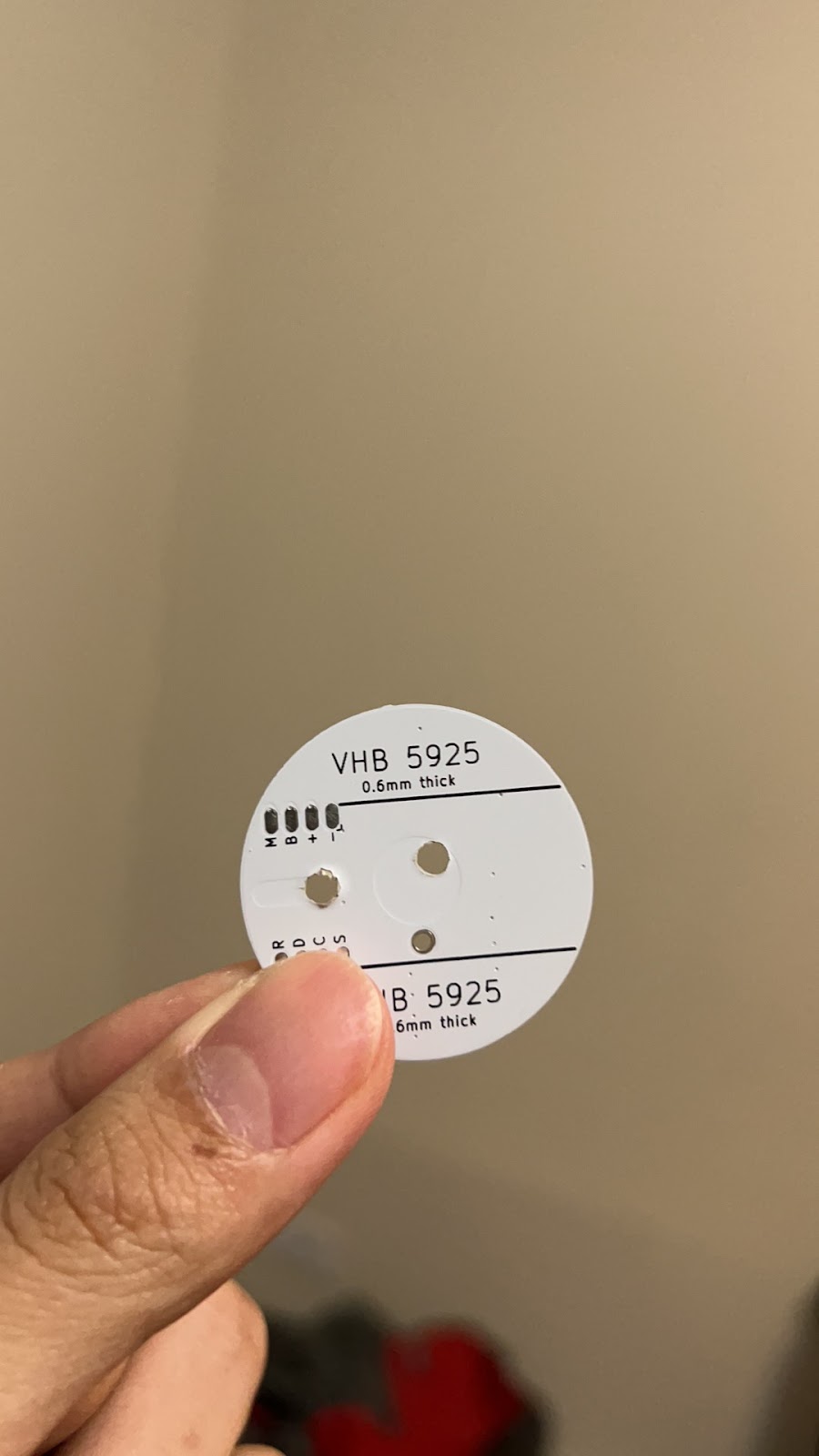
Figure 14. (a) Screen PCB with 2 Holes, (b) The holes We drilled


Figure 15. (a) Screen PCB after Soldering, (b) Soldered Base PCB
3D Printing
We built a set of case and inner part using a 3D printer to support all our components and make it better-looking. The most important part is the connection and the base for BLDC. It is designed thin enough to travel through the hole in the motor’s center, acting both as the tube for screen wires (up to 8 wires in a 2-millimeter diameter hole, and as part of the screen’s stand. Since our 3D printers are not in a high resolution, i.e., the diameter of the extruder and layer height, we cannot build a tube that strong due to limited size. We tried a lot of times, still could not get an ideal mount base.

Figure 16. 3D Models in Z Suite