 Sean Morton
Project Goals
PourFection is a project developed by Lance Go and Sean Morton for their electrical engineering capstone project at Northwestern University, ELEC_ENG 327: Electronic System Design II. The goal of the project was to design a smart coffee brewer that made the pour-over coffee brewing process easy - yet still precise - for users who’ve just rolled out of bed.
The following goals were established for what we wanted our coffee machine to incorporate:
- The PourFection will use a V60 pour over brewer, which is a common brewer used in households across the world.
- The PourFection will be able to boil water for brewing coffee.
- The PourFection will be able to maintain coffee temperature post-brew phase.
- The PourFection will distribute the appropriate volume of water for a given amount of grounds.
- The PourFection will have a companion webapp where the user can track brew metrics such as water usage, coffee weight, etc. The webapp will also allow the user to configure aspects of the brew such as brew ratio and water temperature
The development of the PourFection followed a typical project design process: proposal, initial prototype, full prototype, two revisions, and a final product/report. Over the course of the development process, some design aspects of the brewer changed, a notable example being the water heating method changing from an immersion heater to a kettle. However, the final product ended up being very similar to the original device in mind. Because of some development difficulties, some functionality included in the original proposal was omitted. Firmware setbacks in the later phase of development meant live data charting needed to be cut from the final web app design. On the hardware side, the custom PCB shorted during testing, resulting in the destruction of a 12v-3.3v regulator and the ESP32; consequently, the prototype breadboard was used during the final demonstration..
This article will give an in depth insight into the design, development, prototyping, and construction process of the PourFection Pour-Over coffee brewer.
Component Selection
Some components we wanted to include in PourFection were no-brainers: we bought servos to make the nozzle rotate in the circular pattern, and bought immersible thermistors to measure the temperatures of liquids - and they worked as expected. Other aspects of the project proved more complex: specifically, the heating and delivery of precise quantities of water.
We disassembled two coffee machines and watched videos online to understand how they heat and push water through the system. Drip coffee machines boil small drops of water up through a tube - a method that doesn’t provide the pressurized stream that pour-over coffee making uses. Keurig machines use pressure to push water either (a) into and out of a heating reservoir (for the K150 model) or (b) around a heating element and directly to the K-cup, in the case of some smaller Keurig models.

Credits to Altaf Khan, quora.com.
We decided using pressurized valves wasn’t a good goal for this project, as it would raise the cost and complexity of our project significantly. We also rejected the idea of using solenoid valves that open or close to passively allow water to flow through, as we found it hard to imagine this sort of valve delivering a pressurized stream of water. Instead, we decided to go with yet another option: using a food-grade pump motor to pump water from a pre-boiled vessel of water. We initially considered designing our own fluid vessel and heating it using a 1500W immersion heater; however, this posed practicality and safety concerns, so we just used a kettle as our water boiler.
Component Testing
With so many components involved in our project, it was necessary to carry out independent testing of all components on a breadboard, and to build some special testing rigs in order to verify that the components worked.
The first component we put time and effort into testing was the load cell. Neither of the team members had used a load cell in prior projects, so we were unsure how to properly measure weight readings. The team tried reading from the load cell directly and using a digital low pass filter to get consistent readings, but this proved ineffective. The team then bought a HX711 load cell breakout board from Adafruit and constructed a stand out of plastic and washers, and attempted to measure deflection of the load cell when a mass was placed in the tray.

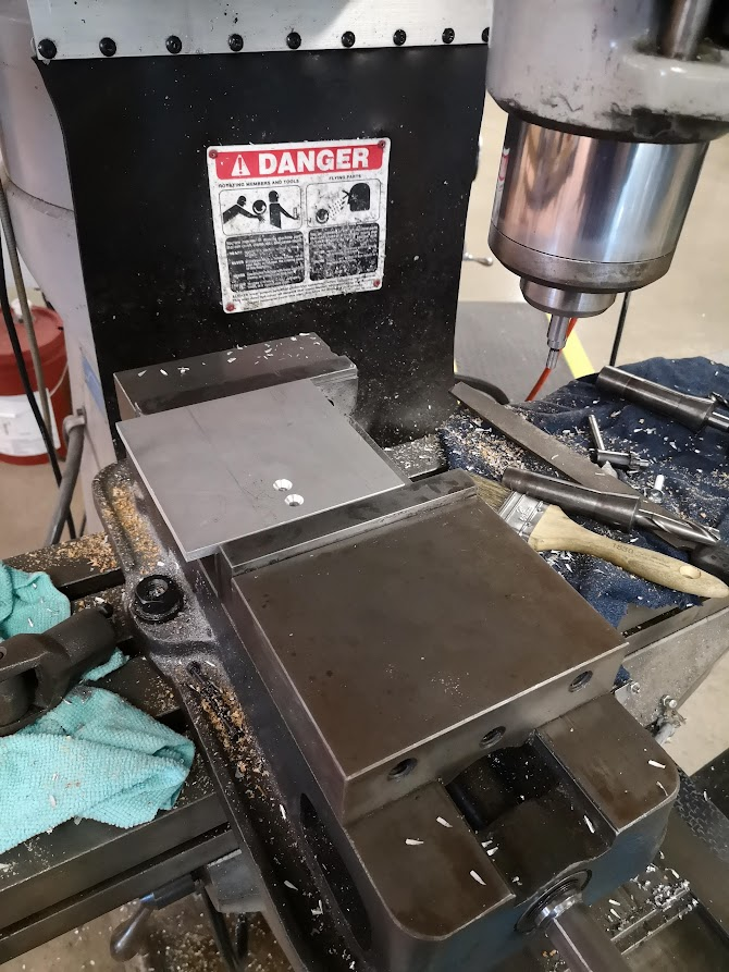
The team noticed some deflection of the plastic (which bent when a load was applied) and of the washers (which compressed against each other like a spring). We didn’t like how much the system bent and oscillated under relatively small loads, so we machined a new base plate out of metal on a Bridgeport mill, and used stiff spacers (individual, not stacked on top of each other) instead of the washers previously used. This made the load cell plate much more rigid, and gave us highly accurate force readings.
The remaining components of the system, including the pump motor/motor driver, inverter, immersion heater/kettle, servos, heating pad, thermistors, and relays, required only garden-variety electronics skills to test. For the breadboarded version of our circuit, we used three breadboard, with different voltage drops across each of the supply rails:3.3V, 5V, and 12V. 12V power was supplied by a 12VDC power supply with screw terminals; 5V power came from an adjustable bench power supply; 3.3V was supplied by an ESP32 connected to a laptop via USB.
When testing the kettle, we took three steps to further protect ourselves from being shocked. Our method for powering the kettle via a relay was to chop off the plug of the kettle, splice together the AC-Neutral wires of the kettle with an extra Mains power cable, and connect the AC-Line wires of the kettle & cable to the relay. Switching Line is preferred over switching Neutral so that 120VAC isn’t present in the post-relay wiring when the relay isn’t active. We used heat shrink tubing to cover the connection between AC-Neutral wires, and we placed several layers of electrical tape below the breakout board that the relays were mounted to, as we wanted to protect the user from the through-hole solder joints that had AC voltage connected to them.

Embedded System
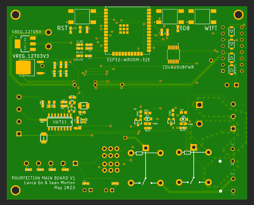
Once all components had been tested and evaluated, a PCB for an embedded system was created in Autodesk Eagle. The main goals of the PCB design were to regulate 120VAC, 12VDC, 5VDC, and 3.3VDC power on the board, to include connectors and screw terminals to interface with the peripherals, and to include pins for programming/debugging the ESP32 over Serial communication.

Build Process
After all components were gathered, and after the PCB was designed, the build began! We started off by designing what we wanted the overall size and appearance of the coffee machine to be - for Lance, who was a team member but also the intended client of PourFection, an extruded aluminum appearance was appealing. We designed the frame to be just wide enough to accommodate the load cell’s base plate, as well as just tall enough to allow the carafe to slide in below the nozzle and rest on the load cell’s tray. Aluminum extrusion was then cut to length on the horizontal bandsaw in the Northwestern undergraduate machine shop.

With a design for the stand in place, we designed how our electronics would mount onto the stand. The servos were zip-tied to each other and to a corner bracket on the central beam of the stand. The pump motor was zip-tied to one of the vertical beams of the frame. As for where the PCB and user pushbuttons went, we thought wood paneling would look really nice on PourFection. We found scrap wood in the machine shop, made designs for side panels, a top panel, and a bottom baseplate. We used OnShape for our CAD due to its online cross-platform compatibility and its ability to easily define variable studios that could be shared across files.
Laser cutting was used to generate precise holes, cutouts, and engravings in the wood (note our custom PourFection logo!). To make precisely-located counterbored holes in the bottom wood plate, we used a Bridgeport mill once again - holes were oversized to 0.29” to allow for slight deviations in location of the ¼”-20 bolts during assembly. Future steps for the physical model that we didn’t get to include sanding all the wood surfaces to smoothness, making the edges of the wood base plate rounded, and applying a cherry finish to the wood to protect it and make it look nice.

Steps for pure-mechanical assembly of PourFection included:
- Assemble all aluminum extrusion.
- Assemble the load cell subsystem.
- Turn the frame on its side. Insert T-nuts, attach the side panels one by one, and insert fasteners.
- Attach the load cell base to the wood base plate using ¼”-20 countersunk screws..
- Attach the wood base plate to the aluminum frame using ¼”-20 countersunk screws. Set the PourFection upright again.
- Attach the two hinges to the top plate and the back plate. Secure with M4 fasteners.
- (later:) Cut lengths of food-grade tubing. One length goes from the kettle to the pump motor; the other length goes from the pump motor output, in through a hole in the wood paneling, and in towards the nozzle.

Assembled!
Steps for electromechanical assembly included:
- Solder all surface-mount components first, paying attention to continuity throughout the board.
- Solder all through-hole components.
- 3D-print spacers to go between the PCB and the rear panel.
- Fasten the power module to the side panel. Solder 12-gauge wire to connect the raw AC-N and AC-L lines with fast-acting fuses.Solder 12-gauge wires that can reach from there to the PCB on the rear panel.
- Add the super-fancy LED/pushbuttons to the front panel, chaining the cathode and anodes of all LED pins, as well as connecting GND to one end of all the button pins.Connect wires from the other end of all LEDs to the screw terminal on the PCB.
- Fasten the PCB to the rear panel. Connect all JST-connector and screw-terminal peripherals at this time (including the kettle, which needs to have its plug snipped).
- Remove the adhesive from the heating pad and stick it to the neoprene liner in the tray,
- Attach servos to a corner bracket, and attach the bracket to the aluminum extrusion.

Assembled, with electronics!
Code: Firmware and Website
Code was written using PlatformIO, which is an extension in VScode which allows you to code microcontrollers like the ESP32. You can use a variety of frameworks for writing firmware in PlatformIO, but we chose the Arduino framework, mostly because it is very simple to work with compared to other methods. This approach also gave us the flexibility that VScode provides while providing the quality-of-life features the Arduino IDE has. Frankly, PlatformIO and the Arduino framework are the best choice for projects like this because of how easy it is to work with and because these types of projects do not warrant fancier development environments. Using something more complicated would have just caused us more headache down the line. We highly recommend PlatformIO for any microcontroller project.
We first wrote firmware for individual components during our testing phase. One advantage of PlatformIO is that it has access to all of Arduino’s libraries and some additional ones registered in the database. For instance, we were able to make use of a servo library to drive our servo motors and the ESPAsyncWebServer libraries for all of our web server needs. This greatly sped the process of writing firmware for a very wide variety of components. After writing the firmware for individual components, we began to consolidate code into our final program. By our first initial revision, 85% of the firmware was already done. As we received feedback from interviewees, we added more functionality and code was added accordingly.

Our firmware’s architecture is relatively simple. Each subsystem (water pump, moving nozzle, carafe, etc.) has its own set of very limited functions. Sensing subsystem functions simply return the values that sensors read such as temperature and weight and electromechanical subsystem functions trigger physical actions such as turning on the pump or moving the servo. These functions are called on by the main loop as needed.
On the front panel, we have three buttons labeled A, B, and BREW. These buttons purge the water line, boil the water, and brew coffee, respectively. Brewing coffee is a multi-step automated process. First, the weight of grounds in the filter is noted so that the correct amount of water can be poured. Second, a bloom phase is started. During the bloom phase, 3x the weight of beans is added in water. We determined this to be about the right amount of water to wet all of the grounds without adding too much water. After the user defined bloom time has passed, the brew phase is started. During the brew phase, water is added in a circular pattern via our moving spout design. This is accomplished by having one servo motor follow a sine wave pattern and the other follow a cosine pattern. After all of the water is added, the servo motors return to their neutral position, ready for another brew.
Because of our limited knowledge of web development and short time frame, we decided to keep the design of our website minimal and functional. At the top of the screen, the main parameters that you can change, such as bloom time, brew ratio, and flow rate, are shown. We also added buttons to turn the heating pad on and off and tare the scale as needed. Ideally we would have liked to add even more parameters, but we were happy with what we had here. Below the main control is live data tracking, which shows the real time measurements of the kettle and carafe temp as well as weight.
It should be noted that the live charts for temperature and weight were not working for our final product. We weren’t sure if it was the WiFi we were using, the Highcharts library, or our own programming errors, but we are leaning towards the latter. Another revision of this project could likely iron out any of the errors we had with the website.

Our Website
Next Steps
We’ve made lots of progress in the 8 weeks we’ve been working on this project, but there are lots of changes that we want to implement to make PourFection a better product. These changes, organized by subsystem, are:
Electrical Hardware
- Redesign PCB to incorporate changes to component layout
- Add better silkscreen labels for components
- Motor JST connector position/size
- Connect LEDs within fancy pushbuttons; make a button press cause the LED to turn off
- Purchase a greater number of spare components to enable fast prototyping
- Buy relays with 3.3VDC coil voltage
Mechanical Hardware
- Sand and stain the wood
- Round the edges of the base plate
- Standardize all panels/ bolts to use fewer unique component sizes
- Re-machine the tray + neoprene liner for the scale with more precision so it wobbles less
- Reduce the number of screwdrivers for the user - go with either all phillips or all flat head drivers (see: screw terms)
- Replace the 2-term screw terminals with something a little less wobbly
- Include heat sinks onto all components with high power consumption
- Reduce cost of components
Website
- Configure data tracking properly; debug current issues with the app
- Add “remote brew” capabilities
- Add better indication of when brew is done; progress bar to track how long it will take for a brew to finish
We hope that you’ve enjoyed reading about our project, and we hope to continue working on it to make a more well-refined coffee machine!