 Ezequiel
Some good articles explaining the speed control of induction motors via V / f strategy are available in:
http://www.electrical4u.com/variable-frequency-drive/
http://controltrends.org/wp-content/uploads/2010/10/VFFundamentals.pdf
In this project, I tried to prevent the microcontroller from performing calculations for voltage and frequency variables. It uses pre-calculated values to load the registers used in the routines, according to the desired output frequency. I will show how these values were obtained (see the spreadsheet with the calculations on the "v-f" tab).
First the frequency. To change the output frequency simply adjust the sine wave refresh rate, ie change the reload value of the timer 0 interrupt counter (variables T_SIN_H and T_SIN_L, which represent the 16-bit word). For more details, refer to the spreadsheet and the 8051 manual, remembering that the timer is in mode 1. The calculated values are shown below.
;VALUES TO BE RELOADED IN SINE´S TIMER, ACCORDING TO THE FREQUENCY
    T_60 EQU 65152D
    T_50 EQU 65075D
    T_40 EQU 64960D
    T_30 EQU 64768D
    T_20 EQU 64384D
    T_10 EQU 63232D
To change the voltage, the option with less calculations in the microcontroller is to vary the amplitude of the sawtooth wave. This is done by changing the step of increasing the timer interrupt 1 (variable STEP_SAW). The variation behavior is inverse, that is, by increasing the wave amplitude, it will be reducing the output voltage.
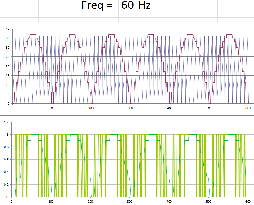
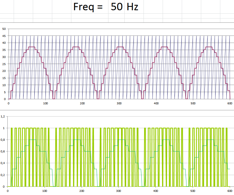
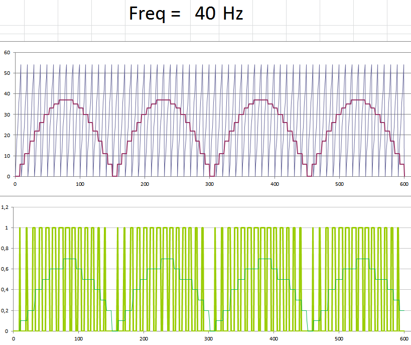
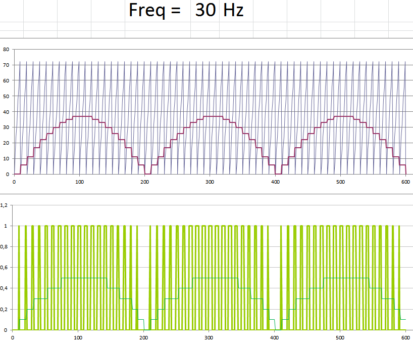
In this case, the challenges were: to find integer increments that produced good resolution in the tension variation; And ensure that the amplitude of the saw is less than or equal to 255 (to fit into an 8-bit word) at all output frequencies. By trial and error method, all parameters had to be adjusted to respect these conditions (including the sine amplitude, 37, remember?). The calculated values are shown below.
;VALUES OF THE AMPLITUDE STEP OF THE SAWTOOTH WAVE, ACCORDING TO THE FREQUENCY
STEP_60 EQU 4D
STEP_50 EQU 5D
STEP_40 EQU 6D
STEP_30 EQU 8D
STEP_20 EQU 11D
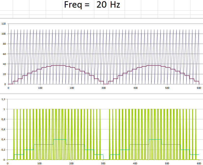
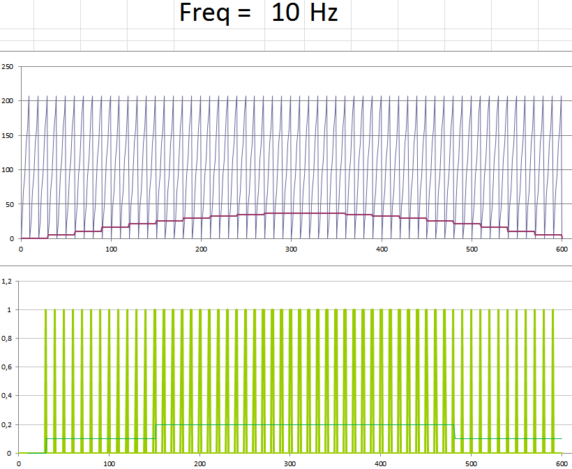
STEP_10 EQU 23DA simulation of the full PWM output can be seen in the "pwm" tab of the worksheet. The following figures show the results (at 10Hz is poor, but acceptable)
Discussions
Become a Hackaday.io Member
Create an account to leave a comment. Already have an account? Log In.