 EtchedPixels
The logic turns out to be fairly simple. The CPU drives the RAM and ROM with the upper lines driven by GPIO lines on the HC11. This avoids the need for any banking logic outside the CPU but at the cost of less flexible memory management. A single gate is needed to make the RAM/ROM work.
The board has a proper reset controller as the 68HC11 can get quite upset if it's not cleanly reset. Some other bits and pieces are needed for the clocking, analogue signal generation and to allow jumpers to put the device into the different supported modes.
Although I've never done it you can in theory program the entire system flash by booting the CPU in serial download mode and downloading a suitable program. The serial mode is also very useful for debugging the board.
As everything runs at 5v the SPI/SD needs to have level shifting so the generic Arduino ones work well. There are two CS lines but to use both requires well behaved SPI devices or a mux on the DO lines from the devices. It's possible to repurpose my SC126 fix board for this with the added advantage it gives you 3 or 4 devices (4 requires you've got one you can safely dummy select to use as "no device" to the others). It's thus possible to also run a Wiznet interface.
Project files are on: https://github.com/EtchedPixels/Mini11

 Keith
Keith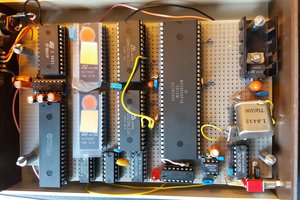
I like the trend I've been seeing lately of SBCs made from obsolete microprocessors. Saw one recently that was Arduino form-factor and pin compatible, but with a 6502 chipset.
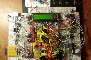
Love to see more detail on this one, and perhaps some pictures. Sounds really interesting.