 Estudio Roble
Advantages of Training Reflexes
Training reflexes offers a series of advantages and benefits in both daily life and various sports fields. Some of the most notable advantages are as follows:
- Improved coordination: Training reflexes strengthens the connection between the brain and muscles, resulting in more precise and rapid movements in various physical and sports activities.
- Faster reaction speed: Trained reflexes enable the body to react more quickly to unexpected stimuli or situations. This is particularly useful in fast-reacting sports such as tennis, boxing, or soccer, where a swift response can make a difference.
- Increased personal safety: By improving reflexes, individuals can react more efficiently to dangerous or accident-prone situations. This can be crucial in everyday activities like driving or navigating crowded areas.
- Reduced risk of injuries: Quick and accurate reflexes help protect the body by responding appropriately to sudden movements or risky situations. This reduces the chances of muscular or joint injuries and falls.
- Cognitive stimulation: Reflex training challenges the brain and keeps it active. This can have broader cognitive benefits such as improved attention, concentration, and overall mental agility.
- Enhanced sports performance: In sports that require fast movements and instant reactions, such as tennis, basketball, or soccer, training reflexes can significantly impact performance. Athletes with well-developed reflexes have a competitive edge as they can anticipate and respond quickly to their opponents' actions.
In summary, training reflexes offers benefits ranging from improved coordination and reaction speed to increased personal safety and sports performance. Additionally, it stimulates the brain and can contribute to better overall cognitive functioning.
It's frequently used by e-gamers and marial artists. Following a video featuring Vasyl Lomachenko using one of these devices.
How Does It Work?
During the training session, the system guides you through the exercises with visual cues, audio prompts, and interactive challenges. It measures your response time and accuracy, providing real-time feedback on your performance. This feedback helps you track your progress and identify areas for improvement.
If connected to a PC, the system can keep a record of your training progress, including your reaction times, accuracy, and overall performance. This allows you to monitor your improvements over time and stay motivated to continue training.
By regularly engaging in reflex training sessions and progressively challenging yourself, you can experience significant improvements in your reflexes, coordination, and reaction speed.
A Quick Reference is available (in Spanish):
Cobra v1.2 - Guia Rapida v1.pdf
Power On
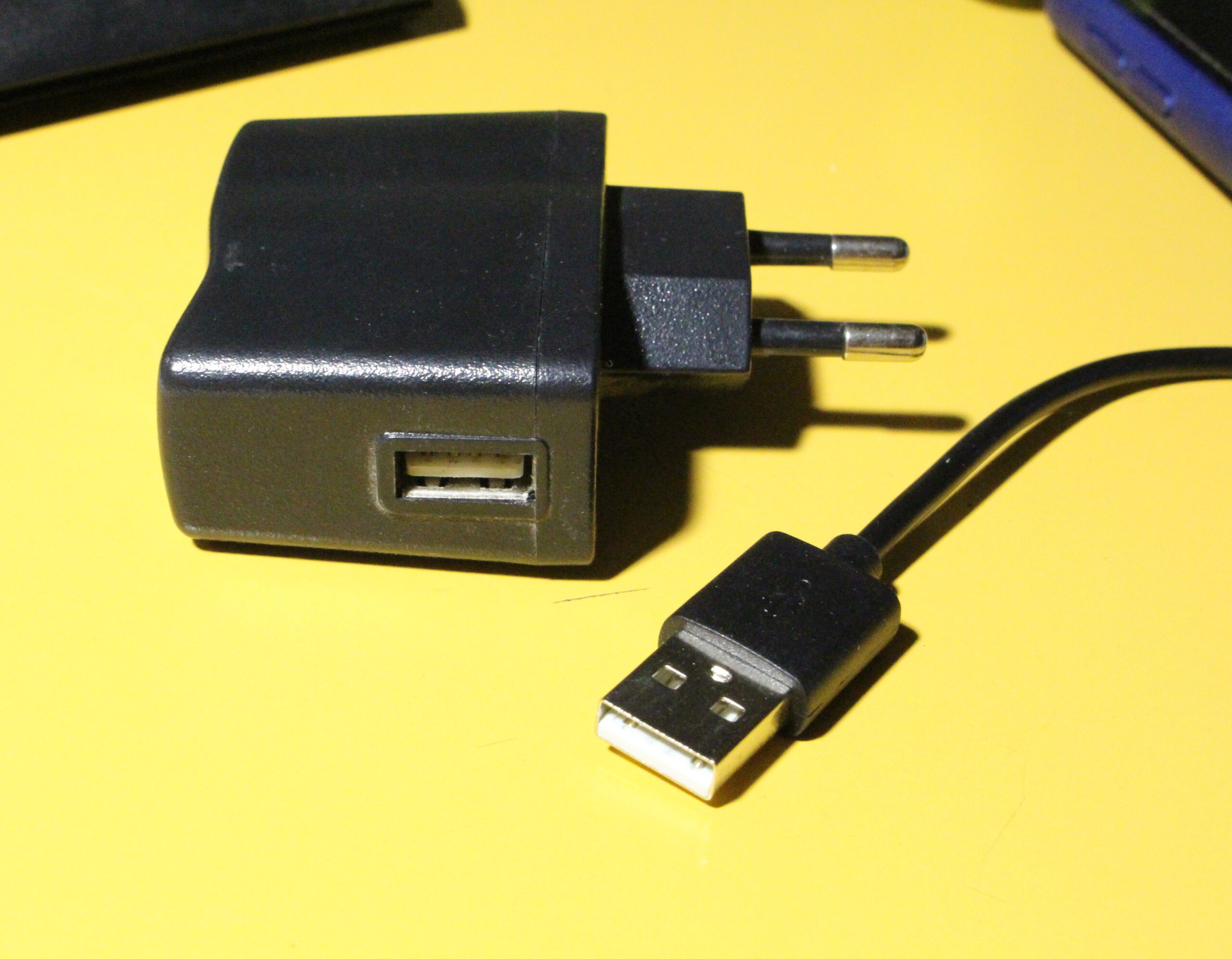
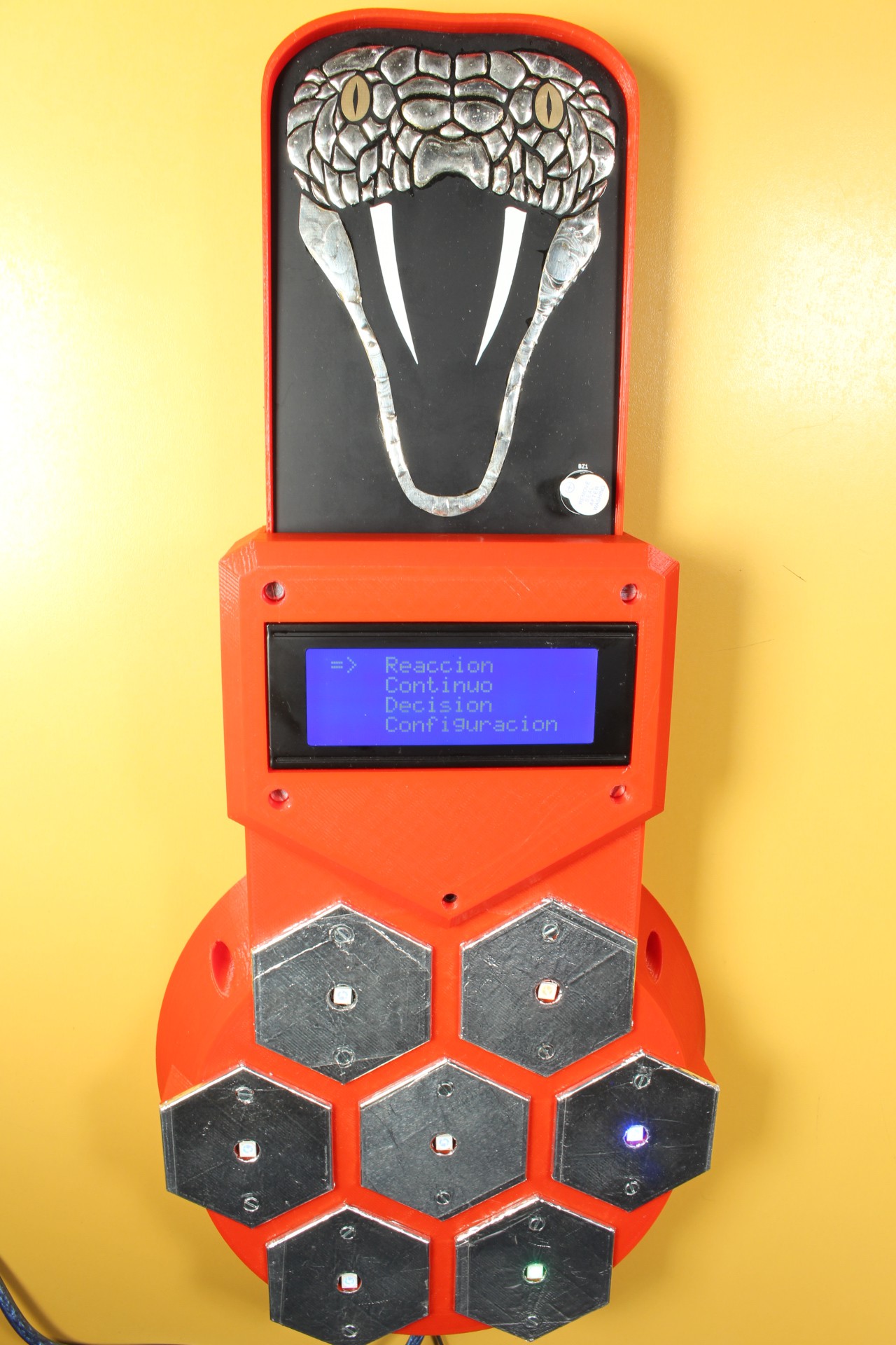
To power it on, you just need to connect the USB cable to a power supply. After a welcome screen, the Training Menu appears.
Menu
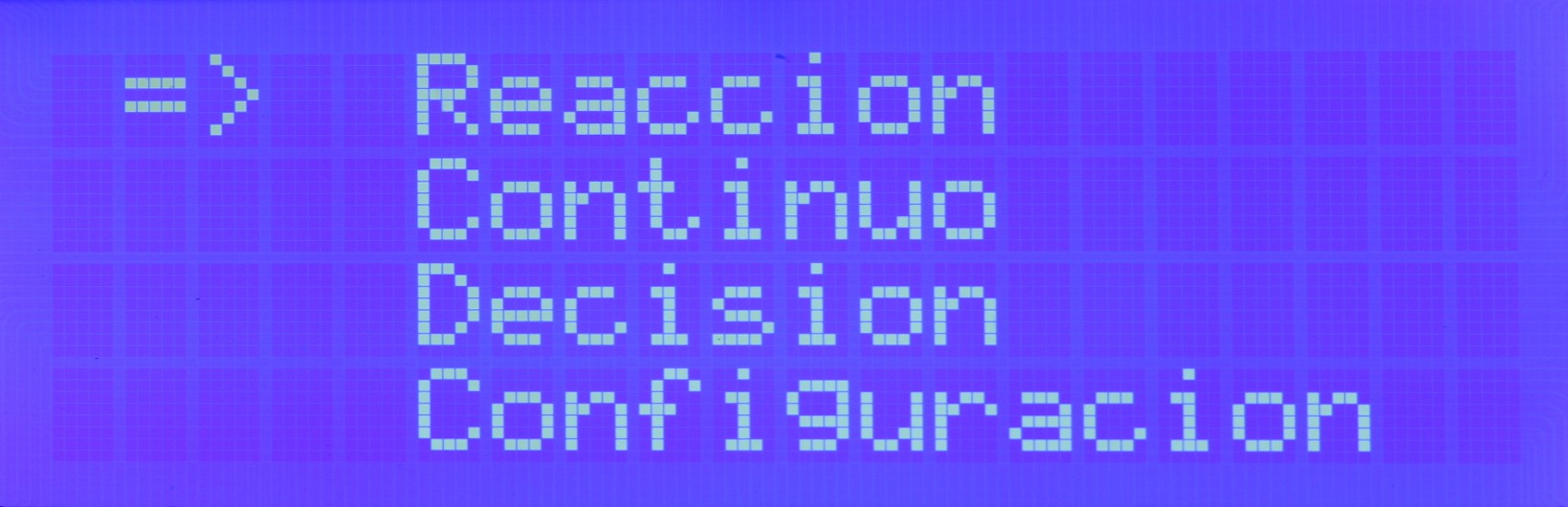
The Training Menu allows you to select different exercises and customize your training session. You can choose from a variety of reflex training exercises, such as reaction time drills, hand-eye coordination tasks, or simulated sports scenarios.
Once you've chosen an exercise, you can customize its difficulty level and duration based on your preferences and training goals. The system provides options to adjust the speed, complexity, and intensity of the exercises to challenge your reflexes effectively.
The currently selected option is displayed with the cursor: =>
You can change the option using the lit-up pads:
- Red: Up
- Green: Down
- Blue: Enter the selected option.
Training Modes
Reaction
A randomly lit red pad will start flashing. You must press it as quickly as possible. There is a random waiting time between each press and the next pad lighting up.
The screen displays the repetition number, reaction time, and statistics (maximum, minimum, and average reaction times of the series).
Continuous
Similar to the Reaction mode, but without any waiting time between repetitions.
Decision
Randomly, either a red or green pad will light up:
- If it's green: Press it as quickly as possible.
- If it's red: Do not press it. If pressed, it will be counted as a mistake.
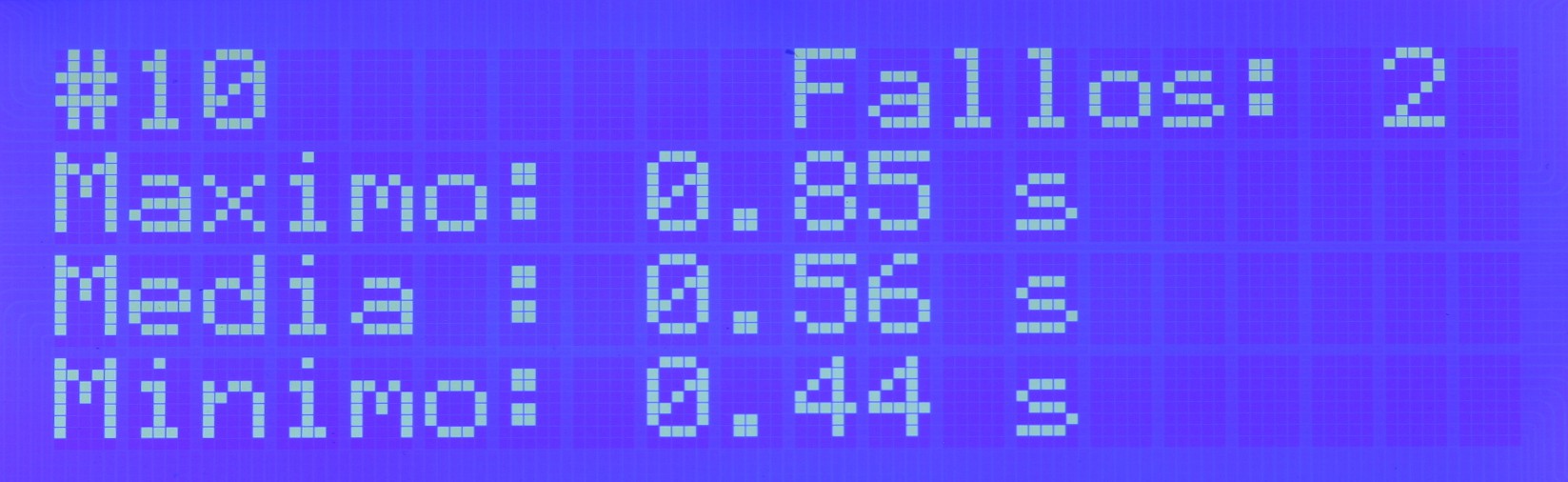
Final Screen

Display the # number of repetitions performed.
The values are:
- Maximum: The longest time. The slowest reaction.
- Average: The arithmetic mean of the times of all repetitions.
- Minimum: The shortest time. The fastest reaction.
In the "Decision" mode, include the number of Mistakes (times the red pad was pressed incorrectly):
Automatic Stop
If more than 2 seconds pass without pressing the pad after the LED lights up, the program will be aborted, and it will return to the main menu.
This value can be modified with thesquama value in the firmware.
Configuration
By entering the configuration, you can change the number of repetitions.
- Red pad: Increase the number.
- Green pad: Decrease the number.
- Blue pad: Set the value.
Hardware
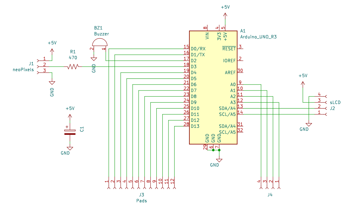
Schematic
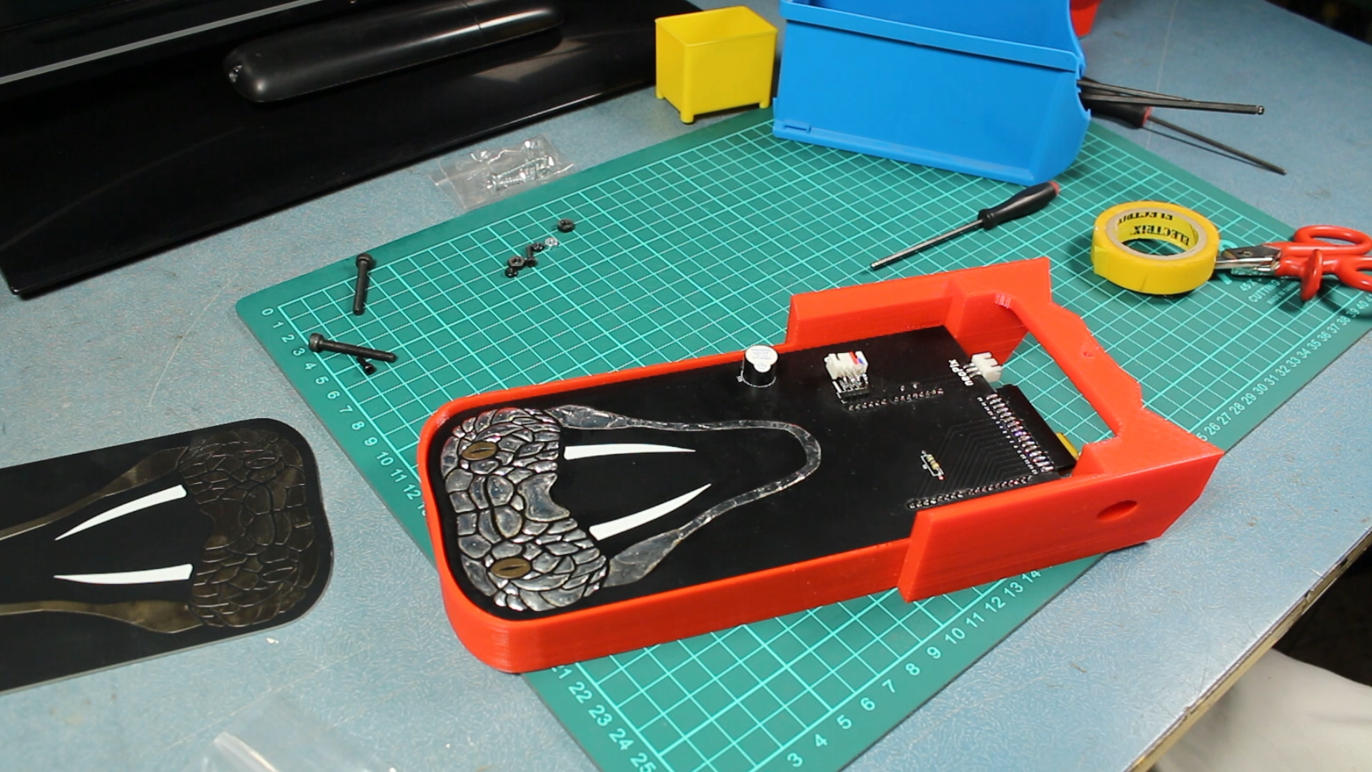
Extraordinarily simple. The PCB acts as a shield for the Arduino. It incorporates a buzzer, the resistor, and the capacitor for neopixel protection, as well as the connectors for:
- LCD I2C
- Neopixeles
- 14 pads
PCB
Designed using KiCad EDA.
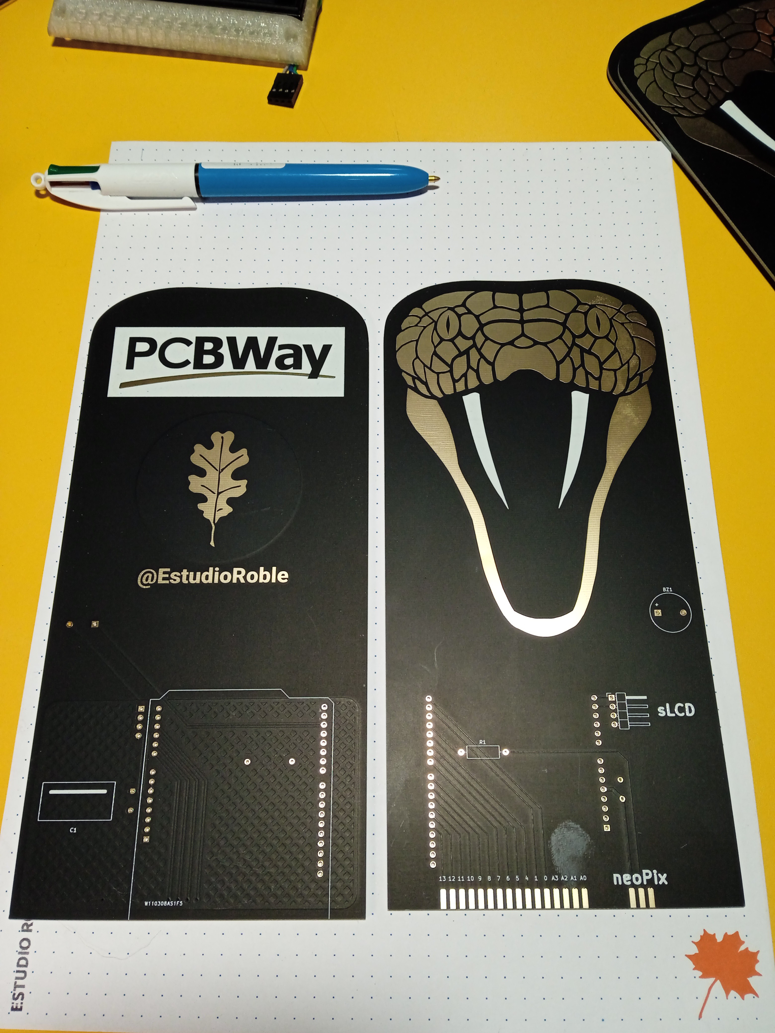
The PCB has been proudly manufactured by:

It has dimensions of 203.1x96mm and a thickness of 1.6mm. It consists of 2 layers. The base material is FR-4: TG130. The finish is Immersion gold (ENIG). The solder mask is Matte Black, and the silk screen is White.
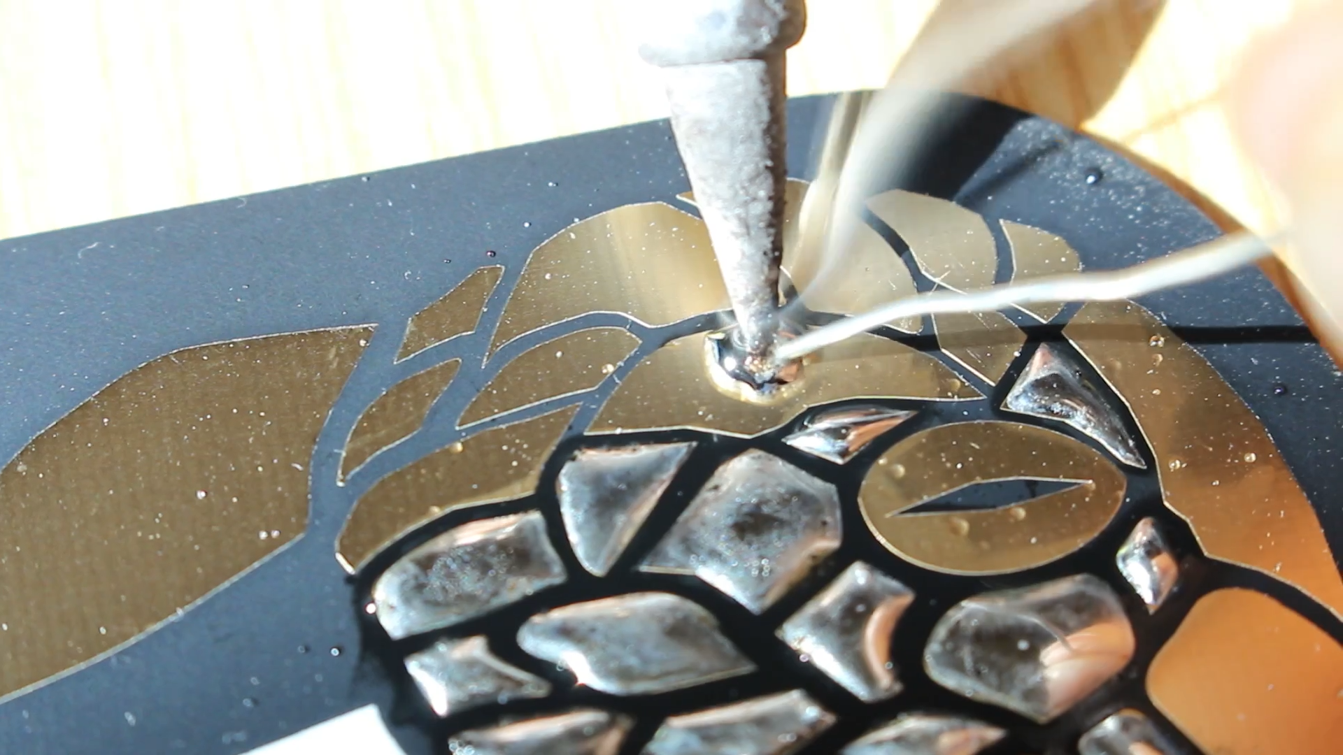
The squama of the Cobra have been filled with solder.
Capacitive Pads
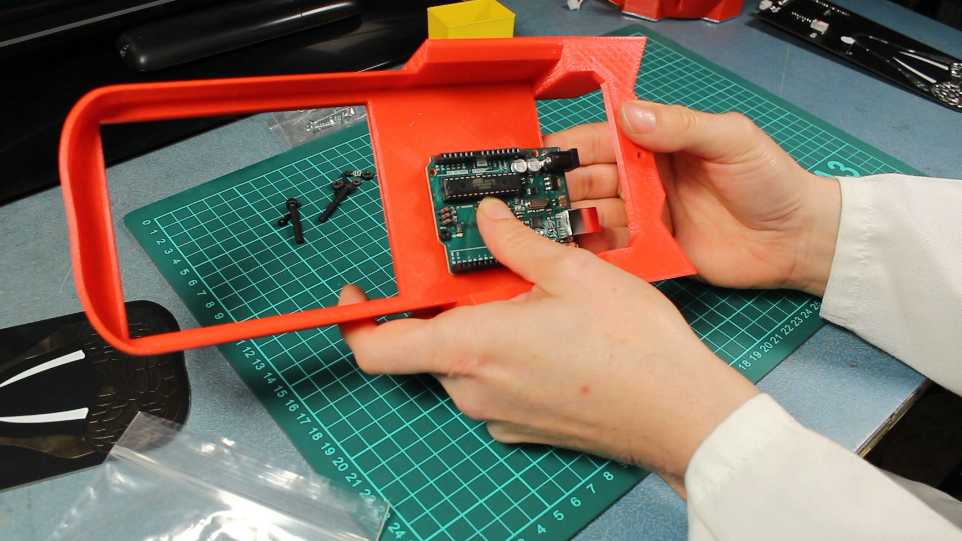
Hexagonal pads printed in 3D have been coated with conductive aluminum tape. One of the two fixing screws is used to connect the cable to an Arduino input. In the center, a neopixel is installed.
The connections to the Arduino are made randomly. To establish which pad corresponds to which input, we turn on the neopixels successively and print the input number to the serial port using the following software:
We incorporate them into the software using the matrix:
int neoPix[] = {99, 99, 99, 99, 99, 99, 99, 1, 0, 2, 6, 3, 5, 4}; // Pad index, gives the neopixel number. 99 for unused pins
Although only 7 pads are connected, everything is prepared to add another 7 external pads.
3D Printed Parts
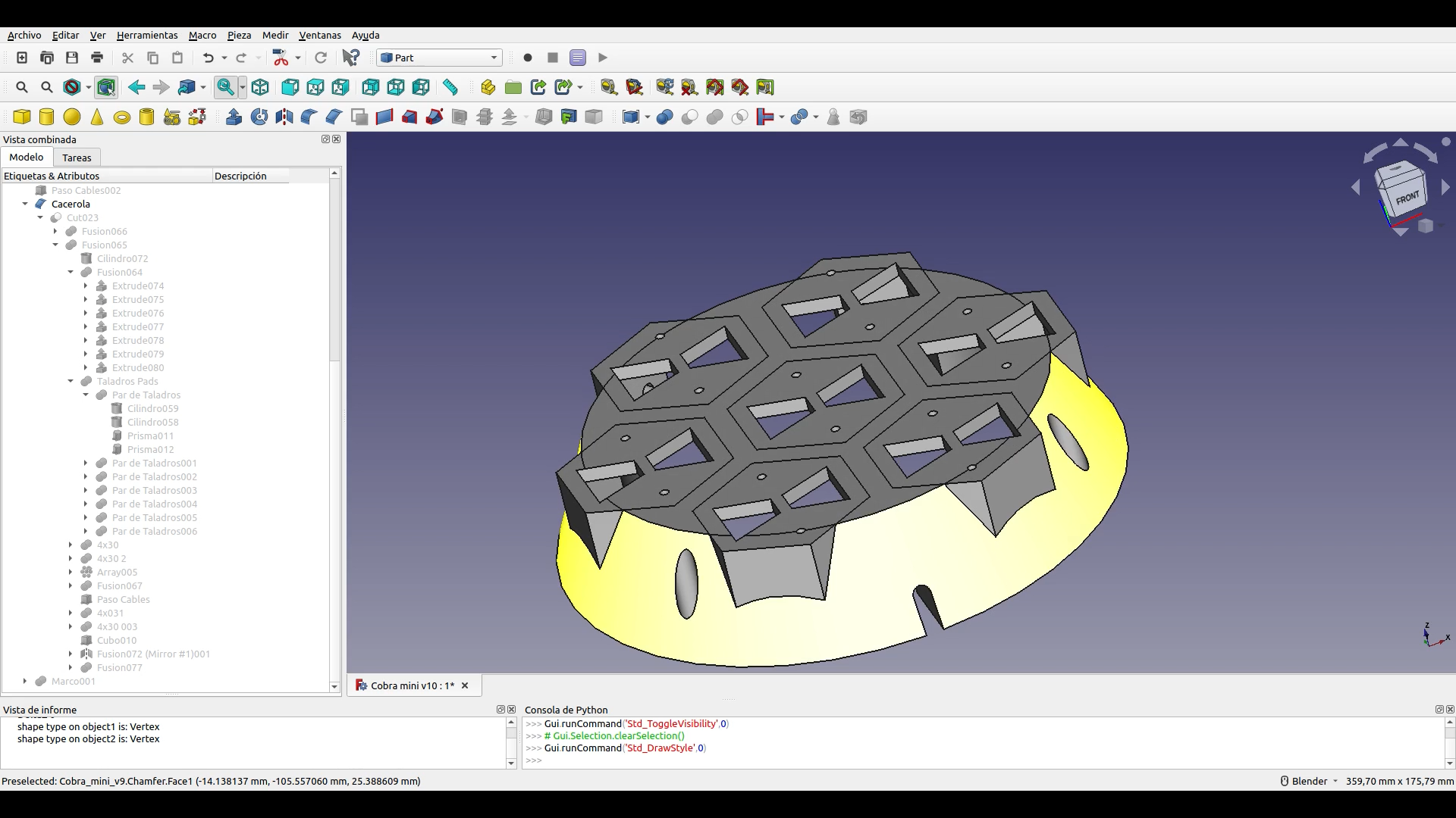
All parts have been designed with the freeCAD software. You can download the design file in freeCAD format and the .stl files of the parts from here:
Software
You can program it using the Arduino IDE.
State Machine
The software is structured as a state machine defined by the 'machineState' variable.
...while (machineState == 0) { // init MENU
...while (machineState == 8) { // MENU
...while (machineState == 1) { // Reacción
...while (machineState == 2) { // Continuo
...while (machineState == 3) { // Decision
...while (machineState == 4) { // init Configuración
...while (machineState == 5) { // Configuración
...while (machineState == 9) { // Ended
Capacitive measurement of touch pads
The capacitive measurement is performed by the 'readCapacitivePin' function, defined as described in "Native Capacitive Sensors without additional Hardware"
uint8_t readCapacitivePin(int pinToMeasure) {
  // Variables used to translate from Arduino to AVR pin naming
  volatile uint8_t* port;
  volatile uint8_t* ddr;
  volatile uint8_t* pin;
  // Here we translate the input pin number from
  //  Arduino pin number to the AVR PORT, PIN, DDR,
  //  and which bit of those registers we care about.
  byte bitmask;
  port = portOutputRegister(digitalPinToPort(pinToMeasure));
  ddr = portModeRegister(digitalPinToPort(pinToMeasure));
  bitmask = digitalPinToBitMask(pinToMeasure);
  pin = portInputRegister(digitalPinToPort(pinToMeasure));
  // Discharge the pin first by setting it low and output
  *port &= ~(bitmask);
  *ddr  |= bitmask;
  delay(1);
  uint8_t SREG_old = SREG; //back up the AVR Status Register
  // Prevent the timer IRQ from disturbing our measurement
  noInterrupts();
  // Make the pin an input with the internal pull-up on
  *ddr &= ~(bitmask);
  *port |= bitmask;
  // Now see how long the pin to get pulled up. This manual unrolling of the loop
  // decreases the number of hardware cycles between each read of the pin,
  // thus increasing sensitivity.
  uint8_t cycles = 17;
  if (*pin & bitmask) {
    cycles =  0;
  }
  else if (*pin & bitmask) {
    cycles =  1;
  }
  else if (*pin & bitmask) {
    cycles =  2;
  }
  else if (*pin & bitmask) {
    cycles =  3;
  }
  else if (*pin & bitmask) {
    cycles =  4;
  }
  else if (*pin & bitmask) {
    cycles =  5;
  }
  else if (*pin & bitmask) {
    cycles =  6;
  }
  else if (*pin & bitmask) {
    cycles =  7;
  }
  else if (*pin & bitmask) {
    cycles =  8;
  }
  else if (*pin & bitmask) {
    cycles =  9;
  }
  else if (*pin & bitmask) {
    cycles = 10;
  }
  else if (*pin & bitmask) {
    cycles = 11;
  }
  else if (*pin & bitmask) {
    cycles = 12;
  }
  else if (*pin & bitmask) {
    cycles = 13;
  }
  else if (*pin & bitmask) {
    cycles = 14;
  }
  else if (*pin & bitmask) {
    cycles = 15;
  }
  else if (*pin & bitmask) {
    cycles = 16;
  }
  // End of timing-critical section; turn interrupts back on if they were on before, or leave them off if they were off before
  SREG = SREG_old;
  // Discharge the pin again by setting it low and output
  //  It's important to leave the pins low if you want to
  //  be able to touch more than 1 sensor at a time - if
  //  the sensor is left pulled high, when you touch
  //  two sensors, your body will transfer the charge between
  //  sensors.
  *port &= ~(bitmask);
  *ddr  |= bitmask;
  return cycles;
}
This function grounds the pin first. Then it sets it to a high level and measures the time it takes to reach that level. The higher the capacitance coupled to the pin, the longer it will take to reach the high level, and the further we will go in the "else if" sequence, and the higher the value of "cycles" will be. In the following video, you can see that the time it takes for the pin to rise is greater when it is touched with the hand, thus increasing its capacitance. The value of "cycles" is represented on the background screen (not very visible). It increases when touched.
Touched!
A threshold value is set: "int threshold = 5" that determines when the pad is being touched and when it is not.
capPin[0] = readCapacitivePin(pin[0]);
    if (capPin[0] > threshold) {
      // Se está tocando el pad
    } else {
      // No se está tocando el pad
      }