The purpose of this project was to monitor a well water level 100' away from the house in the back yard with no available power supply. The project was orignally done with a Raspberry Pi Pico W but decided to go with a ESP32-Wroom-32U for the external antenna.
This project has three options:
Option 1: Fixed Positon Solar Panel
Option 2: Scanning Solar Panel (scans all positions every 30 mins)
Option 3: Tracking Solar Panel (Based on GPS Coordinates)
_XpR21b8a2o.jpeg?auto=compress%2Cformat&w=740&h=555&fit=max)
_Zp5Fkx1cgF.jpeg?auto=compress%2Cformat&w=1280&h=960&fit=max) The ESP32 collect the sensor data and sends the data to InfluxDB and then imported to Grafana for trending and visulization over Wifi. InfluxDB Cloud & Grafana in this project are free and allow for 30days of historical data. You would need to setup accounts and obtain your InfluxDB token and create your dashboard. I will not go over this process in this built as a simple google search can give you some examples how to setup the accounts and just replace "<Your Token here>", "<Your bucket here>" & "<Your Organization>" in the provided code to publish the data to InluxDB.
The ESP32 collect the sensor data and sends the data to InfluxDB and then imported to Grafana for trending and visulization over Wifi. InfluxDB Cloud & Grafana in this project are free and allow for 30days of historical data. You would need to setup accounts and obtain your InfluxDB token and create your dashboard. I will not go over this process in this built as a simple google search can give you some examples how to setup the accounts and just replace "<Your Token here>", "<Your bucket here>" & "<Your Organization>" in the provided code to publish the data to InluxDB.


Wiring Diagram explanation:
Power(+) from both the battery and the solar panel is run through a 4 pin switch to elminate all sources of power while working. I found that both the Solar input and battery input needed to be switched or the ESP32 would not shutdown due to the voltage from the solar panel. Ensure your switch does not connect these two sources as they have different voltage potenitals.
Each power source is run through its own INA226 to measure the voltage, current and power then connected to the Solar Power Management Board by DFRobot. More information on the board can be found here: https://www.dfrobot.com/product-1712.html
3.3V and ground is supplied to the INA226s from the ESP32 and SDA/SCL for communiation.
The ESP32 is connected to the Solar Power Management Board with a USB cable to provide the power supply to the ESP32.
The ESP32 supplies the 5V+/- to the level sensor and pin 33 is used for the analogue signal from the level sensor. Important to note that the level sensor selected has a higher range then the well can get too so the output voltage from the sensor does not exceed the limit for the ADC on the ESP32. A 10M Range level sensor was used for a well that is 7M deep and the output voltage of the sensor at max range is 4.5V so at 7M the voltage would be around 3.3V
(7 - 0) / (10 - 0) = (V - 0.5) / (4.5 - 0.5). V ≈ 3.3V
If this is not possible in your situation a voltage divider could be used to drop the voltage instead
ESP32 Pins 21/22 are used for the communciation from the INA226s and the light intensity module.

Code Breakdown (Fixed Solar Panel):
MicroPython script designed for an ESP32 microcontroller. Here's a breakdown of its functionality:
Importing Libraries: The code starts by importing various libraries required for different functionalities, such as networking, timekeeping, hardware control, and sensor readings.
GPIO Configuration: The code configures the GPIO pins defined in the <b>gpio_pins</b> list as inputs with pull-down resistors. It also disables the Bluetooth functionality by setting the pin 0 as an output and setting its value to 0.
I2C Initialization: The code initializes the I2C interface using the <b>SoftI2C</b> class with specified SCL (clock) and SDA (data) pins.
INA226 Device Initialization: The code initializes two INA226 devices connected via I2C (0x40 and 0x44 addresses). It sets the variables <b>ina1</b> and <b>ina2</b> accordingly and flags <b>I2C1_connected</b> and <b>I2C2_connected</b> to indicate successful connections.
LED Initialization: The code initializes an LED pin (pin 2) as an output.
Blinking LED: The code defines a timer event (<b>timer1</b>) that toggles the state of the LED using the <b>blink</b> function. It then blinks the LED once by setting its value to 1.
ADC Initialization: The code initializes an Analog-to-Digital Converter (ADC) object for a specific pin (pin 33).
WiFi Configuration: The code defines the SSID and password of the WiFi networks in the <b>WIFI_NETWORKS</b> list. It also includes a function <b>connect_to_wifi()</b> that attempts to connect to each WiFi network sequentially until a successful connection is established.
Device Connection: The code includes a function <b>connect_devices()</b> that attempts to connect to the INA226 devices via I2C.
Sensor Data Collection: The code defines a function <b>send_sensor_data()</b> that collects sensor data, including pressure, battery current, battery voltage, battery power, solar current, solar voltage, solar power, and CPU temperature. The data is then formatted into InfluxDB line protocol strings and sent to an InfluxDB Cloud server using HTTP POST requests.
Main Execution: The code initializes variables, sets constants for light sleep time and watchdog timeout, and starts an infinite loop.
The code resets the watchdog timer, reconnects to devices if necessary, connects to WiFi if not connected, and tracks consecutive failed WiFi connection attempts.
Sensor data is collected and sent to InfluxDB Cloud using the <b>send_sensor_data()</b> function. If the data transmission fails, it increments a failed transmissions counter and continues the loop.
If data is sent successfully, the LED blinks and the failed transmissions counter is reset.
The code then enters a light sleep mode for the specified duration and repeats the loop.
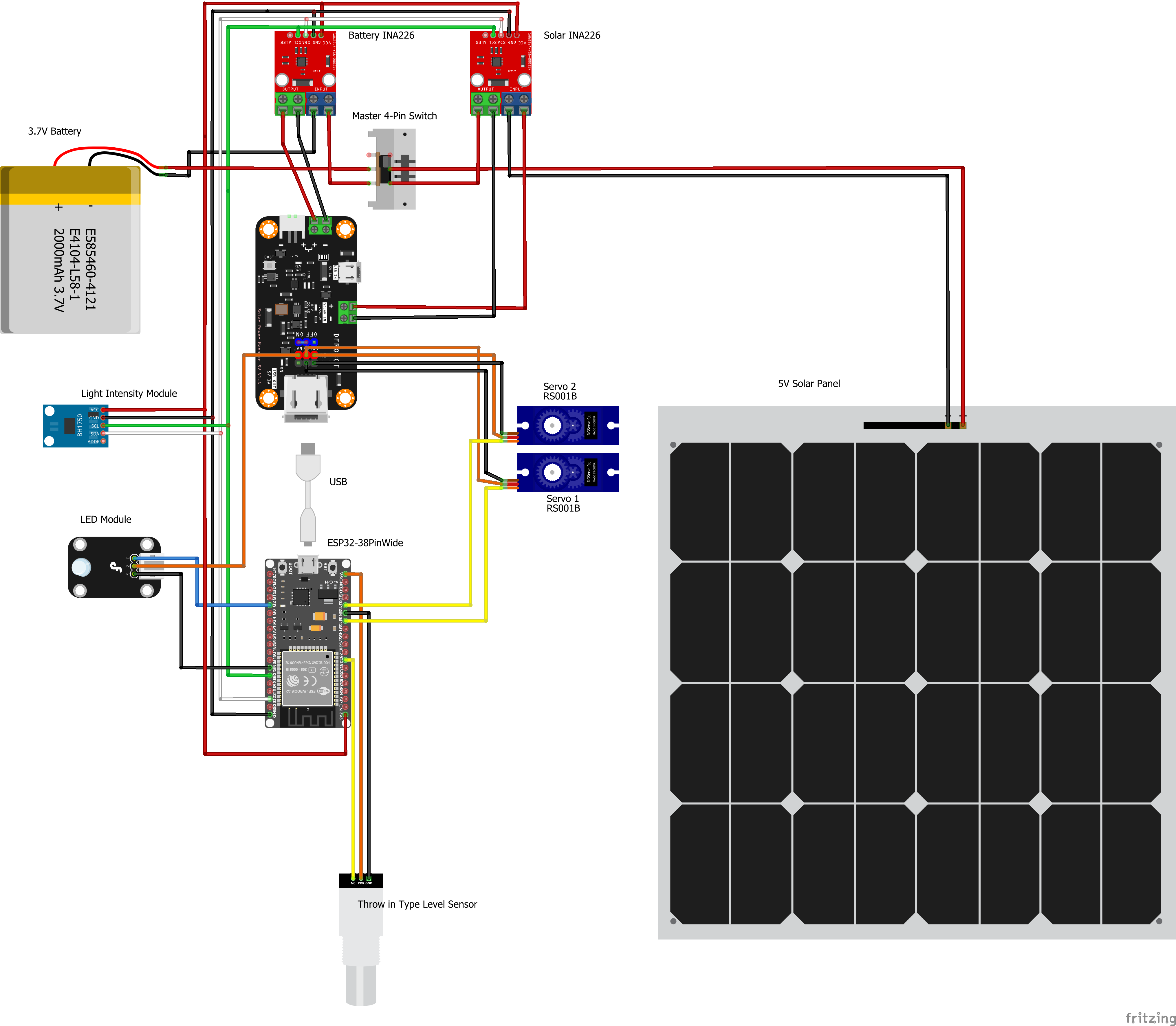
Wiring Diagram for Sun Tracking Solar Panel (both versions):
The wiring diagram is essentially the same but two servos are added and a light intensity module to display the sunlight intensity in W/m2. Remember the Solar Power Management Board by DFRobot can only handle 1A so enure you use micro servos if you decide to connect it the Solar Power Managemet Board. Otherwise you can provide another DC to DC buck converter off of the battery for the servos, keep in mid th stall current of the servos as this would be the worst case, you could also fuse the power supply to the servos to protect from overcurrent.
Code Breakdown (Sun Postion Tracking Solar Panel GPS Coordinates) Option 3:
MicroPython and is designed for an ESP32 microcontroller. Here's a breakdown of its functionality:
- The script imports various modules and libraries required for different functionalities.
- It configures GPIO pins and sets unused GPIO pins as inputs with pull-down resistors.
- Bluetooth is disabled by setting the corresponding GPIO pin to a low value.
- PWM (Pulse Width Modulation) is initialized for servo motor control.
- Global variables are defined to store various parameters and sensor readings.
- LED pins are initialized for status indication.
- A timer is created to handle LED blinking.
- Functions are defined for connecting to Wi-Fi networks, connecting to devices, synchronizing time, and retrieving the current time.
- Functions are defined for moving the servos, calculating the position of the sun, checking sunrise conditions, and controlling tracking based on altitude.
- Functions are defined for reading sensor data such as well level, battery status, solar status, light intensity, and CPU temperature.
- The script executes various initialization steps such as connecting devices, synchronizing time, and moving the solar panel to the sunrise position.
- The main loop of the script continuously performs the following actions:
- Connects to a Wi-Fi network.
- Retrieves the current time.
- Calculates the position of the sun.
- Checks if it is sunrise and adjusts the servo positions accordingly.
- Checks if tracking is enabled based on the altitude and tracking flag.
- Reads sensor data such as well level, battery status, solar status, light intensity, and CPU temperature.
- Sends the collected data to an InfluxDB Cloud server.
- Blinks LEDs to indicate the status of the script.
- Enters a low-power sleep mode for a specific duration.
- Repeats the above steps.
Code Breakdown (Sun Postion Tracking Solar Panel) Option 2:
MicroPython and is designed for an ESP32 microcontroller. Here's a breakdown of its functionality:
- Importing modules: The code imports various modules required for different functionalities, such as networking, timekeeping, machine control, and sensor interfaces.
- GPIO pin configuration: The code sets up a list of GPIO pins and configures them as inputs with pull-down resistors. It also disables Bluetooth by setting pin 0 as an output and driving it low.
- I2C initialization: The code initializes the I2C interface using software I2C on pins 21 (SCL) and 22 (SDA).
- INA226 and VEML7700 device initialization: The code attempts to connect to INA226 devices on addresses 0x40 and 0x44 and a VEML7700 device on address 0x10 via I2C. If the connection fails, it prints an error message.
- Servo motor control initialization: The code initializes PWM for controlling two servo motors using pins 13 and 12. It also defines functions for moving the servos and sets servo angle limits.
- LED control: The code initializes an LED pin and a timer for blinking the LED. It defines a function for toggling the LED state and sets an initial state for the LED.
- ADC pin configuration: The code sets up an ADC object for pin 33 and configures its attenuation.
- WiFi network configuration: The code defines a list of WiFi networks with their names and passwords.
- WiFi connection: The code defines a function to connect to a WiFi network using the provided list of networks and passwords. It attempts to connect to each network until a successful connection is established or all networks have been tried.
- Device connection: The code defines a function to connect INA226 and VEML7700 devices via I2C. It attempts to connect to each device and sets flags to indicate the connection status.
- Best sun position calculation: The code defines a function to find the best sun position based on power and light intensity measurements. It scans vertically and horizontally, adjusting servo angles and measuring power and light intensity using INA226 and VEML7700 devices.
- Sensor data collection: The code defines a function to collect sensor data, including pressure, current, voltage, power, and temperature readings. It uses ADC and INA226 devices for data collection.
- Data transmission: The code defines a function to send the collected sensor data to an InfluxDB Cloud instance. It creates InfluxDB line protocol strings for each data point and sends them via HTTP POST requests.
- Main loop: The code enters a main loop that runs continuously. It performs the following tasks:
- Resets a watchdog timer at the start of each loop iteration.
- Checks the connection status of INA226 and VEML7700 devices and attempts to reconnect if necessary.
- Connects to the WiFi network if not already connected.
- If connected, finds the best sun position and sends sensor data to InfluxDB Cloud.
- If not connected, attempts to connect to the WiFi network and increments a counter for failed WiFi attempts.
- Sleeps for a duration before starting the next loop iteration.