 Keenan Pinto
The whiteboarding/brainstorming session was helpful in identifying that there are two particular Users or Customers or "people who could find this interesting".
To ensure that it appeals to both types, the project requires a DIY version and Ready-to-use (RTU) version. However given that they both do the same thing on a fundamental level, there is an opportunity to have common parts at the PCB stage and then fork things at the enclosure stage.
The last revision of the PCB which would probably have been V2 if I had been naming versions consistently, was a smaller size than the potential enclosure. This wouldn't be an issue for the RTU version, but for the DIY version (especially if using the MicroBit) it would make the footprint of the enclosure smaller than I would have liked.
The functional elements of the board are
- Microcontroller - BBC Micro:Bit or Wemos D1 mini (Esp8266)
- DC-DC step-down converter (12V to 3.3V)
- NeoPixel ring (12 LEDs)
- DC air pump (3V)
- TCS3472 colour sensor board with white LEDs
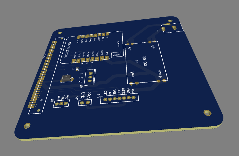
Here's the schematic
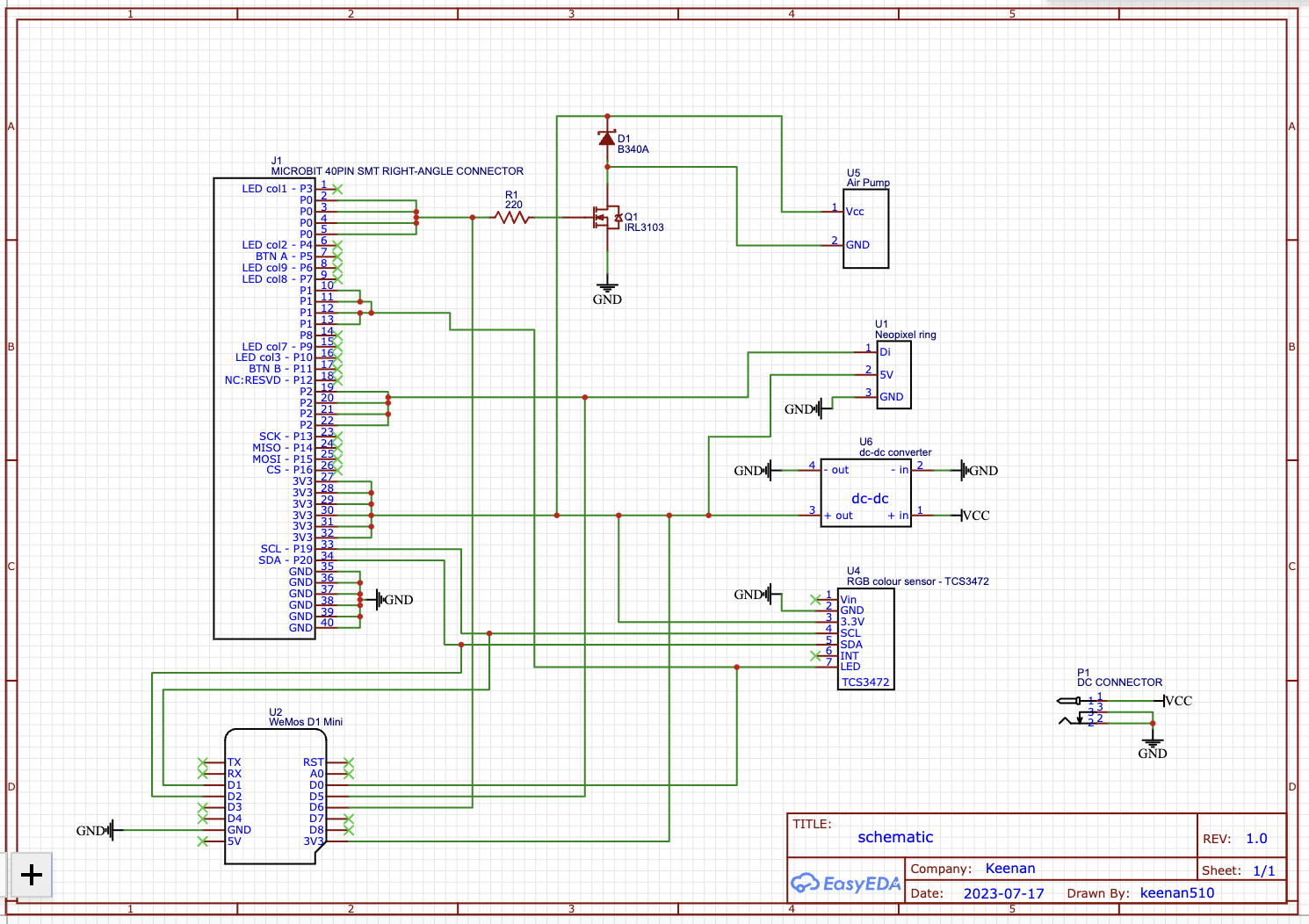
The PCB design was fairly straightforward. One of the choices made to simplify the assembly process was the use of JST connectors. The idea behind this was that it would make the electronics part of the DIY version a bit easier if it was being used in a workshop context.
I was also interested in having the functional blocks be added like LEGO so I chose to use a module for the DC-DC converter rather than building the circuit onto the board.
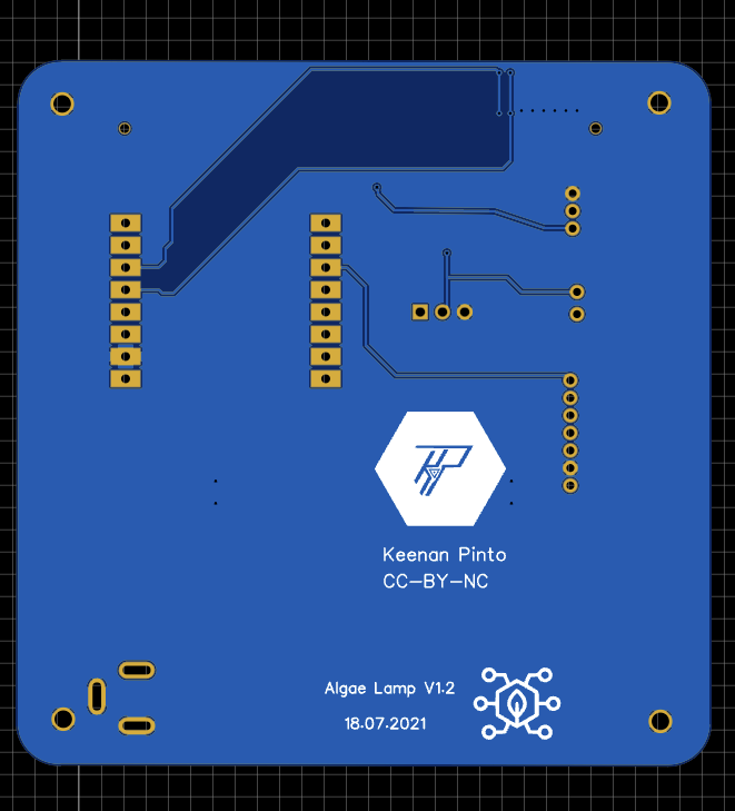
Here's an image from the EasyEDA editor.
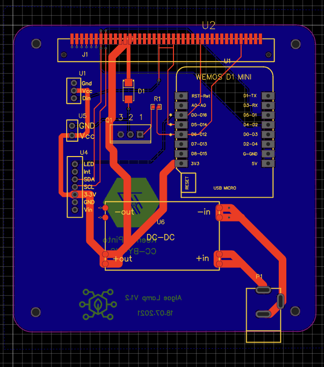
Followed by 2D views...
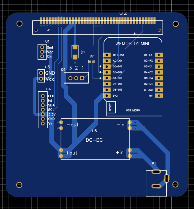
Since I manually created most components, the 3D view wasn't too different from the 2D.
In the next revision, I'll make use of the components that EasyEDA have in their library so the 3D view looks better.
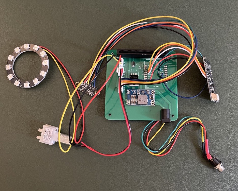
After getting the boards fabbed from JLC PCB and purchasing the BOM, I received the parts and settled down to assemble the board.
After everything was done, when I went to test it, I found out that my Wemos D1 mini was no longer working :(
Rather than dive headfirst into the wormhole of trying to fix the Wemos board, I chose to replace it with a Lolin 32 that I had lying around. It needed jumper wire to match the connections of the Wemos bit was a pretty good drop in replacement.
Finally, an electronic setup that's ready to test. This is what it looked like.
So what comes next? I think I will do another revision of this board but for now, it works.
Once the mechanical enclosure is completed, I will post an assembly and test log.
Discussions
Become a Hackaday.io Member
Create an account to leave a comment. Already have an account? Log In.