Intro
I’ve been using pulse response testing in one form or another since the early probe prototypes – basically applying a pulse to the probe input and capturing the output on a scope. It’s a quick way to estimate the probe’s bandwidth with a minimal test setup. This log describes pulse response methods and recent testing with latest prototype.
The simplest form of pulse testing goes like this:
- Apply a pulse to the probe input and capture the result on a scope
- Measure probe output rise time, from 10% to 90% amplitude
- Divide the probe output’s rise time by 0.35 to derive its bandwidth in Hz.
This method ignores the scope's limited bandwidth and the source’s non-instant rise time. Because of this, it will underestimate the probe’s bandwidth somewhat. But there's an equation to compensate for this error, which I'll apply in the testing below.
First steps - building and characterizing a pulser
The probe's rise time is pretty fast. Its design bandwidth of at least 150MHz implies a rise time of 2.33 ns or less. So we'll need a fast pulse generator. I didn't have one, but luckily high speed logic gates came to the rescue! I used that approach to build a minimal pulser shown below. It's 74LVC1G14 Schmitt trigger inverter set up as a relaxation oscillator. There's a resistor divider at the inverter's output to reduce loading and achieve an approximate 50 ohm source impedance. The output is through an SMA connector at the top of the photo. The connector sticking out the side is for the power supply.

The setup below is aptly a miminal setup for characterizing the minimal pulser. It's connected right to the scope's input, which is set to 50 ohm impedance.

As you can see the pulse response is pretty flat. The scope measured a rise time of about 804 ps. Not too bad! If we compensate for the scope's analog bandwidth, which is spec'd at 1GHz, the true rise time would a little better at 724 ps.

Applying the minimal pulser
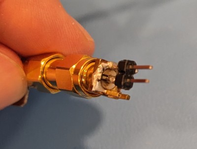
With the pulser characterized, the next step is hooking it up to the probe inputs. That took a little careful soldering to adapt the pulser's SMA output to the probe's pin socket inputs. To do so I soldered a pin header to an SMA connector. I also added in a 50 ohm termination by soldering an 0603 resistor between the SMA connector's center pin and shell.
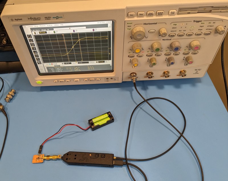
Now we're ready to test! Here's the full setup. There's not too much too - just the pulser, SMA adapter/termination, and probe with its output and power cables.
Here's a scope screenshot showing the probe output and its rise time from 10% to 90% amplitude.

The probe output's measured rise time is 2.12 ns. Using the formula from the Intro section, the probe bandwidth estimate is 0.35 / 2.12 ns, which works out to 165 Mhz. Great! It's within spec.
But remember that this method ignores the scope's limited bandwidth and the source’s non-instant rise time. We can compensate for those with the following formula and should find that the bandwidth is a bit higher than the 165 MHz estimate.

Applying the formula shows that the probe rise time is actually 1.965 ns, which translates to a bandwidth of 178 MHz.
Discussions
Become a Hackaday.io Member
Create an account to leave a comment. Already have an account? Log In.