This log explores recent differential and common mode range testing. I put the probe to its limits and beyond, and captured a bunch of data in the process.
DC differential voltage range testing
What exactly is a differential voltage? I like to think of it as a bipolar voltage supply centered at the oscilloscope's ground. The positive output connects to the probe's "+" input, and the negative output to the "-" input. If you apply such a voltage, the probe should output the same voltage, only scaled by 1/20.
To apply a 1.0 V differential voltage to the probe, you can do the following: (1) Connect the voltage supply ground to the scope ground, (2) set the positive voltage to +0.5 V and apply it to the probe's "+" input, and (3) set the negative voltage to -0.5 V and apply it to the probe's "-" input. The differential voltage across the probe inputs is then +0.5 V minus -0.5 V, which is the 1.0 V that we intended.
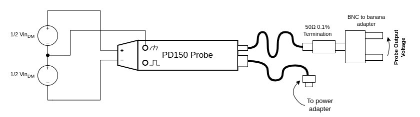
This is essentially the test setup shown below. The bipolar is built with two voltage sources in series, with each providing half of the full differential voltage. They're both labelled 1/2 VinDM. The probe output is set up to connect to a multimeter for accurate DC measurement. I made sure to use a precision terminator built with a 0.1% tolerance resistor to get as accurate results as possible.
Okay, now to the testing! I've got a dual 30V power supply which lets me generate up to +/- 60 V differential. This is nice since I can see how the probe behaves well beyond its differential range spec of +/- 20 V. I set the supply over several voltage points through this range and measured the differential input voltage and probe output voltage at each setting.
After much very tedious work, I filled up the test spreadsheet at last! Here's a plot showing the probe's output voltage as a function of the differential input voltage. The output voltage on the vertical axis is multiplied by 20 to account for the probe’s 20:1 attenuation.
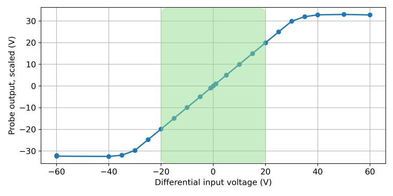
The green section shows where the input voltage is within the probe's specified operating range. In that area you can see that there's a 1:1 relationship +10V in, +10V out, etc. So that looks pretty good. The voltage errors in that region were under 2%.
The performance remains fine up to +/-30V. In fact, you can often use the probe up to that extended range - at frequencies up to about 100 MHz. Beyond 100 MHz, the probe's output voltage becomes limited by slew rate, hence the +/- 20V spec.
Adding some common mode voltage
The differential voltage response is all well and good, but what happens when you apply a common mode voltage too? Well, in a perfect world, nothing would happen! The probe would subtract the two inputs, eliminating any common mode voltage in the process.
Let's give it a try! The test setup needs one slight modification. An extra power supply will need to be connected between the bipolar supply's ground and the scope/probe ground. The new setup looks like this:
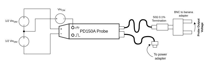
There's a massive combination of possible common mode and differential voltages I could test. To confine things, I focused on the extremes of the probe's common mode voltage spec: +30 V and -30 V. To this end I grabbed one more power supply and wired as in the diagram. I set its output to 30V and otherwise repeated the same exact testing, stepping the differential voltage from -60 V to +60 V. Finally, I repeated this again with the common mode power supply's terminals reversed for the -30 V common mode measurement.
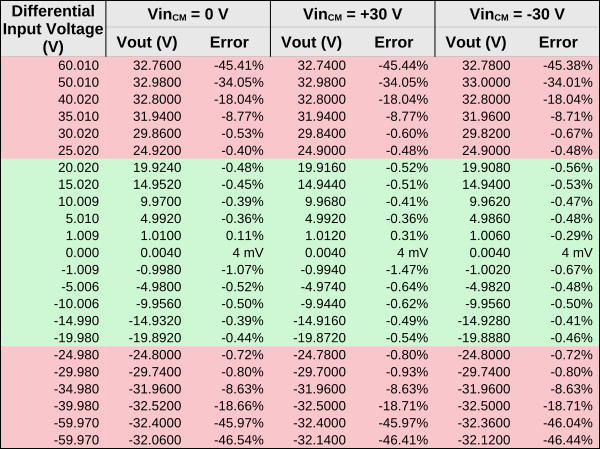
After much more tedious work, I now had in my possession a spreadsheet with two more columns! One column has the data for the +30V common mode voltage, and the other with -30 V. Ideally the test data in these columns should be exactly the same as the previous testing, since the probe shouldn't respond to common mode voltages.
They were in fact very close! Close enough that they would overlap the line in the previous plot and not be visible. So instead, I just put a table of the data here with the data and errors. The green section of the table covers testing where the differential input voltage is within the probe's operating range. In the red sections, it's outside of the probe's operating range.
Conclusion
After all the testing it was a relief to see the probe performing well through its voltage limits. The probe maintained voltage errors of under 2% through its specified differential voltage range of -20 V to +20 V. The performance was nearly identical when applying common mode voltages of +30 V and -30 V.
Discussions
Become a Hackaday.io Member
Create an account to leave a comment. Already have an account? Log In.