Intro
This log describes common mode rejection tests that I performed on the probe. I introduce the test setup and a test fixture, describe the results, and future plans.
For reference, the probe's specs claim a common mode rejection ratio (CMRR) of at least 40 dB at 10 MHz, and at least 70 dB at 60Hz. We'll check these numbers against the test results.
Review of common mode signals and common mode rejection
Applying a common mode signal just means placing the same voltage on both of the diff probe's terminals. Since a diff probe responds to the difference in voltage across its inputs, its output should be zero volts. This is never quite true in the lab. Some common mode voltage leaks through due to imbalances in the probe's attenuator and amplifier.
Common mode rejection ratio (CMRR) describes how well the probe is doing in this regard. It's the ratio of the probe's differential mode gain to its common mode gain. Thus a larger value is better. It's often expressed in decibels when dealing with diff probe specs.
Test fixture
We'll first need a way to apply the same AC voltage across both probe inputs. This is the so called common mode voltage input. In addition It's good to connect the signal source's ground to the probe/scope ground. This ensures that the DC common mode voltage does not drift or have additional AC noise during the test.
I made a simple test fixture for this purpose. It's shown connected to the probe. The fixture is made from a BNC connector, a two pin header, and a jumper wire. The BNC connector's center pin is soldered to both of the header pins. I also soldered a small jumper wire to the ground ring on the BNC connector. This jumper provides the connection to the probe/scope ground. The jumper connects to the probe's ground input, and the non soldered ends of the header to the probe input sockets.
The fixture is shown connected into the middle of a BNC tee adapter. This provides an easy way to connect a signal generator to the fixture, and also to connect a scope for viewing the input voltage.

Connecting it all up
With the fixture ready, we can connect the signal source and a scope to view the results. In the photo below, the function generator connects to the bottom of the BNC tee. The top of the tee connects to scope channel 1. Finally, the probe's output connects to scope channel 2.

Measuring CMRR at 10MHz
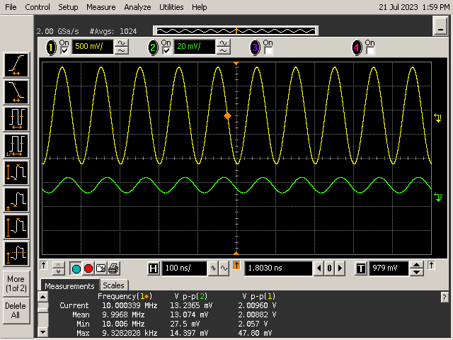
To test at 10MHz, I set both scope channels to 50 ohm input impedance. I also made sure to set channel 2's attenuation to 20X to account for the probe's attenuation in the measurements. I then set the function generator up to output a 10MHz 2 V peak-to-peak sine wave. To maximize effective vertical resolution and measurement accuracy, I set the scope to average 1024 measurements.
The resulting scope traces are shown below. You can see the 2 V peak-to-peak input in yellow, and the probe's much smaller output in green below it. From the peak-to-peak voltage measurements at the bottom of the screen capture, we can compute common mode gain. It is 2.0096 V / 13.2365 mV, or 1/151.8. Since differential mode gain is almost exactly 1.0 referenced to the probe input, we can calculate CMRR as 1/(1/151.8) = 151.8. In decibels, this works out to 43.6 dB, which is within the probe's spec of 40dB or greater.
Measuring CMRR at 60 Hz
I made a couple small changes to the setup for testing CMRR at 60 Hz. At this frequency, we expect a much greater CMRR (of at least 3100:1), causing a correspondingly small signal at the probe's output. In fact the probe pushes the limits of the scope's vertical resolution.
To mitigate this as much as possible, I set my signal generator's output to its maximum output voltage of 20 V peak-to-peak. I then set the scope's channel 1 input to high impedance, since the input is only rated to 5 Vrms when terminated in 50 ohms - anything greater could damage the scope's internal 50 ohm termination. But we don't need 50 ohm termination at such low frequencies anyhow, so high impedance it is.
Here's the resulting screen capture. As you can see, the probe's output is still very tiny even with the large input voltage. I can't zoom in further due to the minimum 20 mV per division vertical setting. So we'll have to rely on using a large number of averages. The resulting CMRR measurement is 6799:1, or 76.6 dB. This is well within the probe's spec of at least 70 dB at 60Hz.

Conclusion
Alright, the testing is complete! The CMRR results back up the probe spec. The only issue is that the probe's output in the 60Hz test is extremely small. It is hard to trust the measurement that well since the scope's minimum vertical amplitude is 20 mV per division. One way to get around this issue is to place a high gain amplifier between the probe's output and the scope's input. It's pretty easy to get lots of gain at 60 Hz using an op amp circuit. I may try that and follow up with the results and see how they compare.
Discussions
Become a Hackaday.io Member
Create an account to leave a comment. Already have an account? Log In.