I've been meaning to show a practical application for PD150 and an opportunity just arose! I'm experimenting with a miniature CRT screen. It uses two deflection coils to steer its electron beam. One coil deflects the beam horizontally and the other vertically. Unfortunately, the CRT's circuitry is pretty specialized for sweeping the beam in a raster pattern, and I want to generate vector graphics. For this I'll need custom drivers for the coils which can output on the order of 20V peak to peak at a frequency of at least 10kHz or so.
What's all this have to do with diff probes? Well, one nice way of generating a large voltage swing is using a bridge driver. And with a bridge driver, neither of the load's terminals are grounded. So you can't just stick a regular probe across the terminals. If doing so, you would need two regular probes, to apply a math function, and to contend with non-ideal imbalances that can get pretty nasty at higher frequencies. This is where the diff probe comes in use. You can just connect it right across the load's terminals without worry and get good test results.
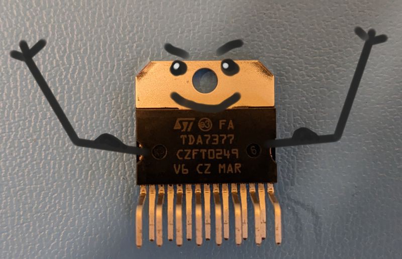
The bridge driver that I've been exploring is a TDA7377. It's an older chip intended for audio amplifier use. It has two 30W bridge outputs, which is perfect since I have two deflection coils to drive. I just bought this one, but it looks like it's been sitting on Mouser's shelves for a couple decades. It's happy to be free!
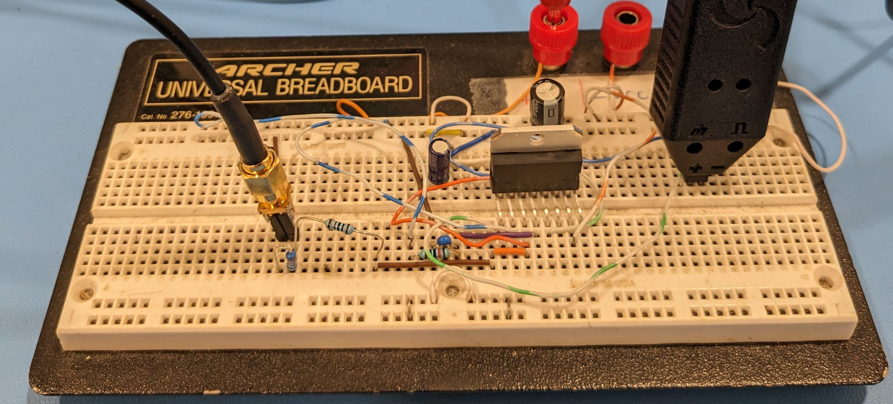
The TDA7377 is a through-hole part, albeit with a strange package that the manufacturer calls MULTIWATT. With a little wrangling, it fits into a solderless breadboard. I have it set up here with an input signal source and the PD150 probe at the output. The input comes through the coaxial cable at the left. The PD150 monitors the output of the bridge on the right side of the breadboard. It's pretty easy to use with a breadboard like this. Just use a two pin header. Place one end in the breadboard. The other end fits right into PD150's input sockets.
Unfortunately the TDA7377's datasheet is pretty sparse. It doesn't even provide a bandwidth. Presumably its response is pretty flat to 20 kHz, being an audio product, but best test it to be sure. Also, I'll eventually need to see how its output performs under the deflection coil inductive loads.
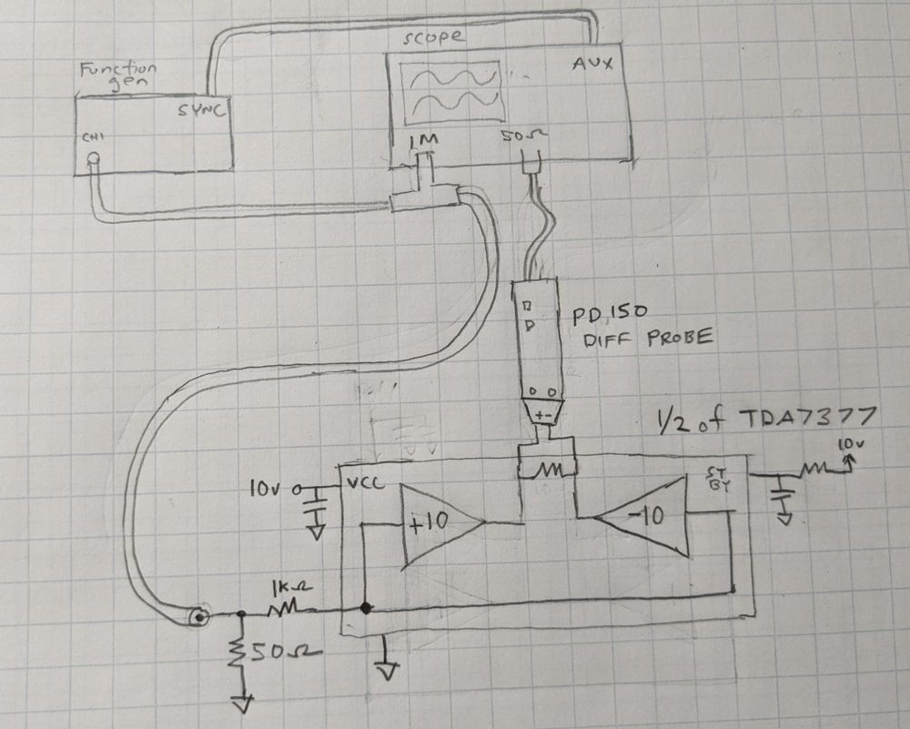
To get started I set up a simple test to measure frequency response with a 10 ohm resistive load. A function generator provides the input. The input path is kept at 50 ohms to ensure meaningful results at higher frequencies. I used the PD150 diff probe to monitor the bipolar voltage across the load. The scope captures the input and output voltages. Here's a diagram of the setup.
Here's the setup on the bench:
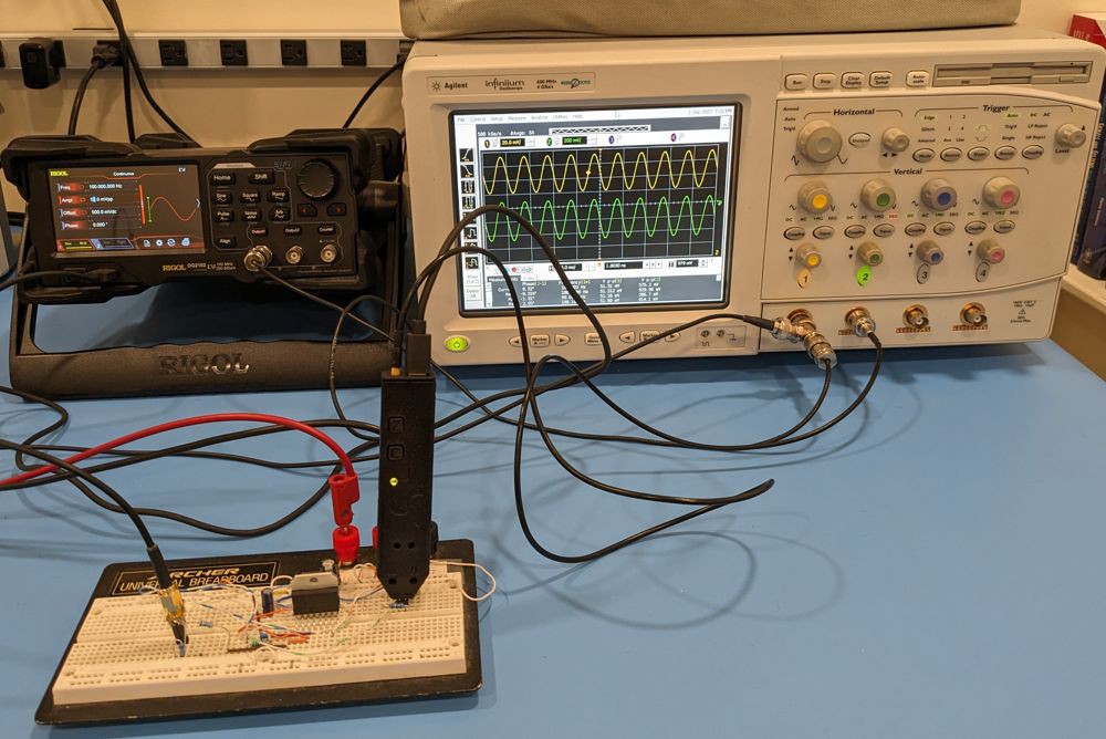
We'd expect the amplifier to behave pretty ideally at a comfortable 1 kHz, and it does. Here's the scope screen with channel 1 showing the input voltage, and channel two showing the bridge output voltage from the PD150. The gain is about 25 dB, which is the lower end of the spec shown in the data sheet.

The response is surprisingly flat to 100 kHz and beyond! Here's the scope output at 100 kHz:
But eventually the amplifier's gain tails off. I found the 3 dB point to be about 535 kHz. Pretty good! I recorded data at a bunch of frequencies and used it to generate a frequency response curve:
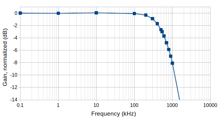
Well that's it for now! It's a good start. With TDA7377's bandwidth being quite high, it was nice having a true diff probe. Had I instead used two regular probes and the scope's math function, I may have run into issues measuring into the 100s of kilohertz. Here both probes, amplifiers, and compensation would have had to be well matched to each other. I was also happy with how the PD150 can plug into a breadboard with a pin header. It was easier than using standard probes with a breadboard.
While this application was for a linear bridge driver, a diff probe is also a good tool for switch-based bridges. These are usually made from four power MOSFETs and used to drive motors, or bridge based power converters.
Discussions
Become a Hackaday.io Member
Create an account to leave a comment. Already have an account? Log In.