 mircemk
Compass is device used for navigation and orientation, and consists of a magnetic needle that is mounted on a pivot and is free to rotate horizontally. The needle aligns itself with the Earth's magnetic field, and scale under her typically has four cardinal directions marked on it: North, East, South, and West.
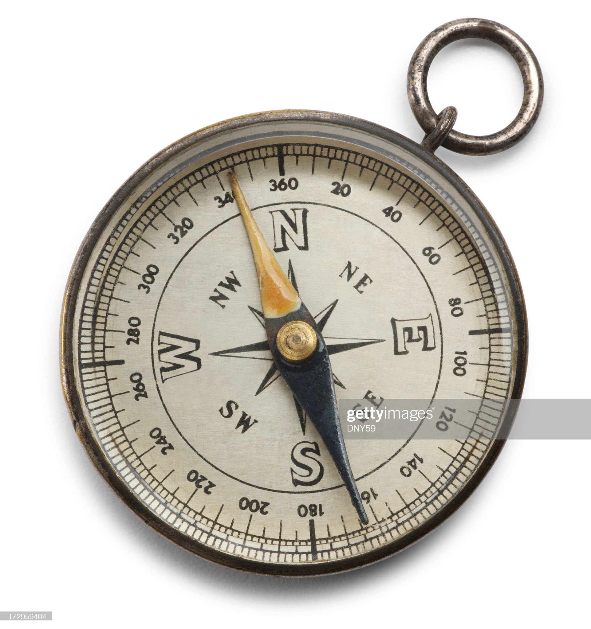
In addition to these four main directions, many compasses also have additional markings indicating the degrees or fractions of a circle.
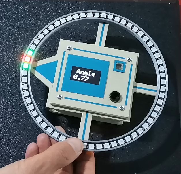
The device presented in the video represents an electronic version of the Compass, where the position of the needle is indicated by group of a three light-emitting diodes.
There is also an Oled display in the middle of the device, which shows the angle relative to the North Pole. In this case the resolution is greater than one degree, while in the case of LEDs the resolution is 6 degrees when moving one diode. When the red diode coincides with the top of the arrow and the value of the angle on the Oled display is about 0 and 360 degrees, then this side is North, opposite to it is South, and East and West are located at an angle of 90 degrees.
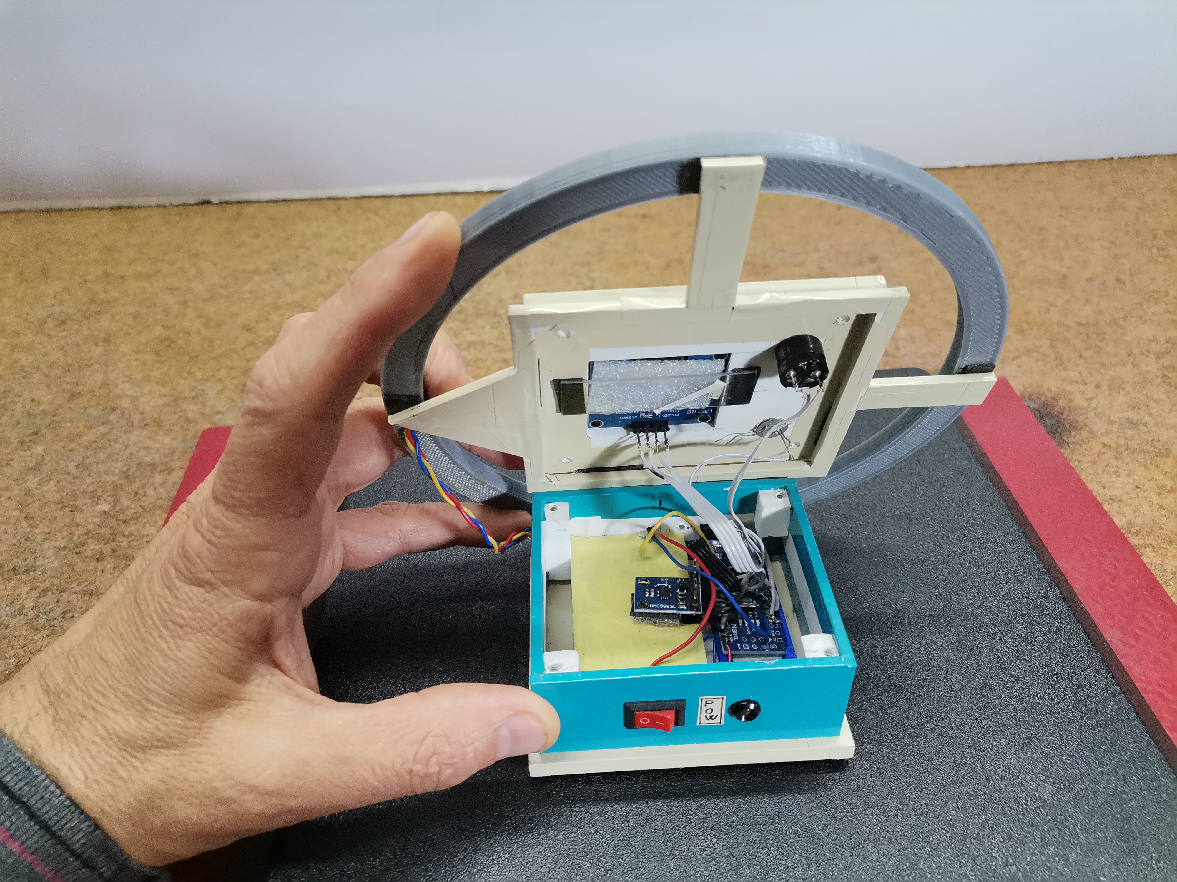
The device is relatively simple to build and consists of several components:
- Arduino Nano microcontroller
- HMC5883L compass module
- Led ring with 60 adressable RGB Leds type WS2812B

If you want to make a PCB for this project, or for any other electronic project, PCBway is a great choice for you. PCBway is one of the most experienced PCB manufacturing company in China in field of PCB prototype and fabrication. They provide completed PCB assembly service with worldwide free shipping , and ISO9001 quality control system. Also, on their site there is an online gerber viewer where you can upload your gerber and drill files to render your board.
The Arduino code is simple as it uses libraries for the Led ring as well as the Compass module. The only modification is conditioned by the fact that we need to enter the declination angle for the specific area for a more accurate result, which we can find it at:
http://magnetic-declination.com/
We also have to calibrate the sensor using the calibration code provided in the library, and input the resulting values into the code in line:
compass.setOffset(27, 200);// Set calibration offset. See HMC5883L_calibration.ino
At the beginning, let me emphasize that the instrument is very sensitive to local magnetic fields and massive metal objects in its surroundings, so the results of this video may deviate to a certain extent. First we need to place the compass in a horizontal position and then turn it on. After the initial logo, a group of 3 LEDs appears on the screen, the two surrounding ones are Green, and the middle one, which represents the direction, is Red.
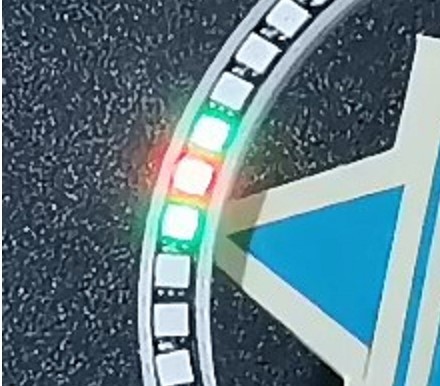
By equating the arrow with the Red Led we get the direction of the North pole. By rotating the compass around its own axis the OLED display shows the angle between north and the tip of the arrow at the given moment. So the Red LED always points North.
In my case I use a box with a oled display from one of my previous projects, and Led ring is mounted in a situable case made of 3D Printer, and below is the .STL file for 3D printing.


so cool work
http://baskino.me/