 joekutz
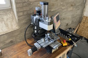
My machine has the following (not) features:
- 4th Axis assembly (see Video 1) : Mini 3-jaw chuck driven by a stepper motor, tail-end support spike thing
- NEMA23 stepper motors
- Lead screws with double thread and 4mm pitch for the X/Y axis
- Probably a 2mm pitch single thread Z-axis lead screw (I need to check)
- Nylon driver nuts (darn, no ball screws / nuts)
- A 40V 12K rpm spindle of unknown power that actually reaches 12K rpm (foreshadowing for a future video)
- CNC Contoller with planetCNC firmware (not licensed I guess, their software does not want to talk to my machine via USB)
Damages found so far:
- Bent main carrier plate that carries the bridge -- Fixed.
- Y-Axis bearing shafts not straight -- Fixed.
- one Y-Axis Bearing block dinged -- Fixed.
- Bent Y-Axis lead screw -- Fixed.
- X-Axis bearings broken and stuck in holes -- Fixed.
- Controller box needs GRBL-Arudino
- Bent X-Axis lead screw
My CNC machine is subject for a comprehensive and ongoing video series on youTube. The seriel will have between 8 and 12 videos at the end, depending on my time. Enjoy.
VIDEO 1 : here I do an initial inspection and talk about my plans with it:
Because I needed to measure some stuff, I decided to buy some old used dial test indicators. Of course, they were broken! I guess when a seller doesn't explicitly says "I TESTED, IT WORKS, TRUST ME!" stuff doesn't work. Sigh. At least, here is a nice video about how I got two old indicators to work fine again.
VIDEO 2: Fixing two old dial indicators
After I had disassembled the machine, more and more outright grotesque damages came to light. There are dents and bumps in some parts, and some stuff that is really hard to bend was bent. I think the machine might be cursed. Here is me fixing and modifying some of these parts.
VIDEO 3: This machine is cursed!
OK, my bearing shafts are not straight, but what does that mean for the machine? How much are they flexing under load, and how bent or straight should they be, so that the machine is precise? And how do I get the bearing block right, that somehow does not fit its bearings? I will find out in video no. 4.
VIDEO 4: Bending and Sanding.
My machine's X-axis is quite wide for being moved by a single lead screw in the middle. Any load off center makes the bridge wanting to rotate sideways. That means that any bearing slack reduces the rigidity and accuracy. Lets find out, whether I can improve that by a bit.
VIDEO 5: Can I improve the rigidity of my bridge?
I inspected my CNC Control Box further to see, how I can optimize the spindle speed control. That part of the project is ongoing. But some details in the box are interesting, so here is a video about it.
VIDEO 6: What is in my controller box?
It is time to tackle another annoyance: The insufficient spindle speed controller. The spindle speed is controlled with a pot knob, but the speed change is slow and sluggish, there is no way to know which position is which speed and the PWM creates an annoying 500Hz whine in the motor. May be we can do better than that, by making our own Arduino-based speed controller.
VIDEO 7: Can I make a better Spindle Motor Speed controller?
 Adrian Prinz
 Extreme Electronics
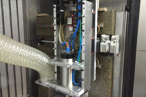
 3D Meister
 Jack Black