Close
0%
0%

Musical Tesla Coil Etched on a PCB

A Musical Tesla coil that is made completely on a PCB

Public Chat
Similar projects worth following
This is a musical Tesla Coil that is completely on a PCB. It creates voltages of around 20 - 30 thousand volts and can play music by connecting to any device with a 3.5mm audio jack. The drive circuitry for this Tesla Coil is not very common and I took the power bridge design from one of Tefatronix's Tesla coil drivers. The main differences between the two circuits is that I used a different feedback method, MOSFET gate drivers, the ability to play music, and the fact that the Tesla Coil is wound on a PCB. Getting this thing to work without blowing up was a big challenge and the final schematic that works pretty well doesn't have PCB design files as I haven't tested the final schematic on a PCB, but it is tested on a prototyping board. All the videos and pictures are of the Tesla Coil working with the final schematic.

Gerber Issues

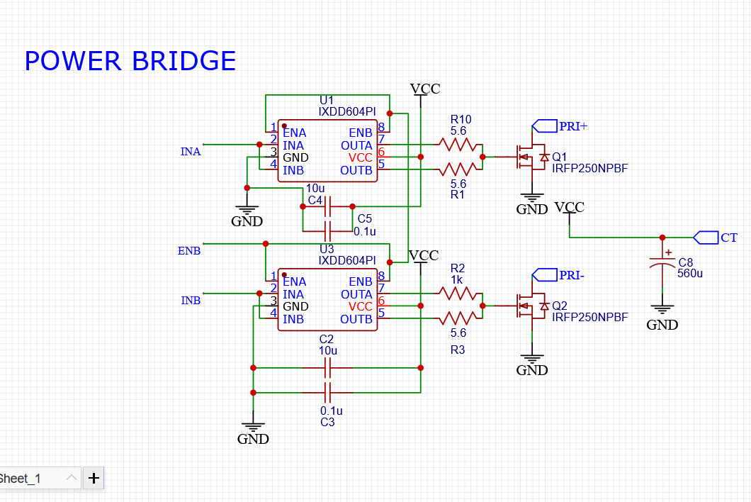
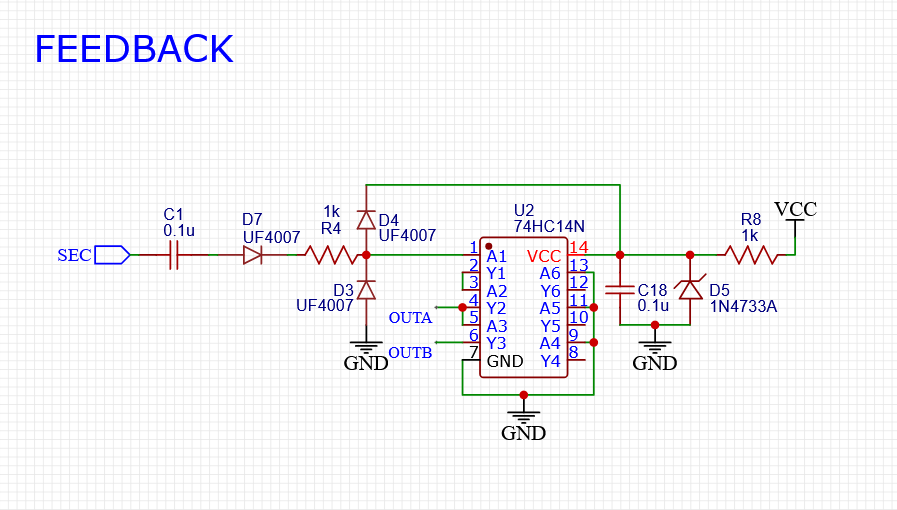
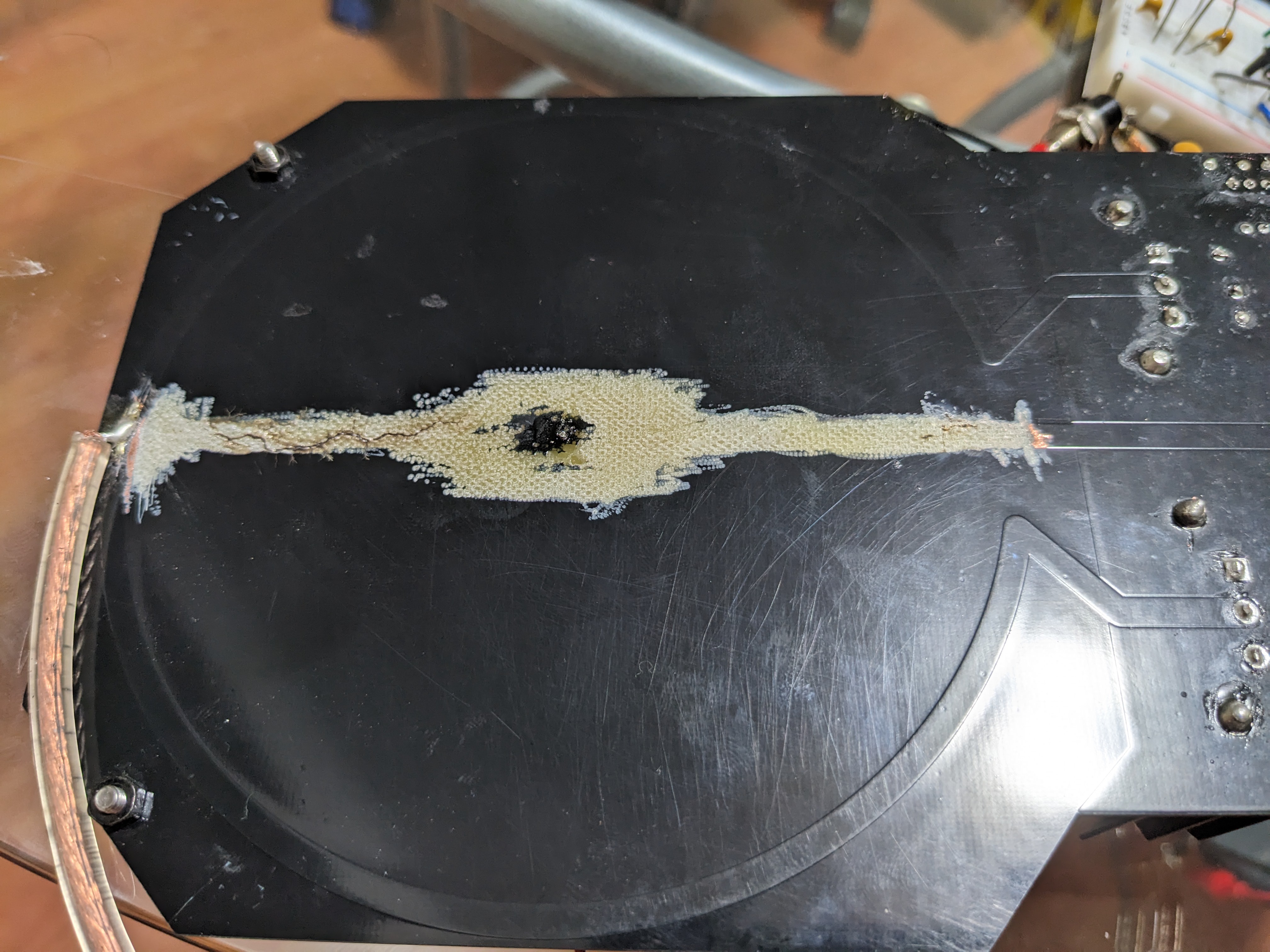
The PCB you see me working with is an old design I had to significantly improve, so those files are also not released as they don't work properly. The PCB files you see is the high voltage transformer only and no drive circuitry, I've tested this transformer with Half and full bridge designs as well as single transistor designs and it worked very well.

VIDEOS OF TESLA COIL IN OPERATION CAN BE FOUND IN "INSTRUCTIONS"

CLICK HERE TO GET THE BOARDS FROM PCBWAY

Gerber_PCB Tesla Coil_2023-07-08.zip

PCB OF ONLY THE PCB TRANSFORMER, NO DRIVE CIRCUITRY.

x-zip-compressed - 18.86 kB - 07/09/2023 at 05:24

Download

BOM.csv

ALL PARTS PURCHASED FROM DIGIKEY

ms-excel - 2.22 kB - 07/09/2023 at 05:24

Download

  • 1
    SCHEMATIC

    FULL SCHEMATIC CAN BE FOUND BELOW

    Power Bridge

    This Tesla Coil uses a push pull power bridge in order to drive the Tesla Coil. When the circuit is first powered on, one of the gate drivers sends a short pulse (this happens when the enable pin of the gate driver goes high) and current flows through half of the primary winding, since the high voltage PCB Transformer has a center tap labelled as "CT". This causes a magnetic field to be generated and induces a current in the transformer which then creates a magnetic field at the coils resonant frequency where this resonant frequency is fed to the feedback circuit which then sends a clean square wave signal back to the gate drivers keeping the oscillation going. The gate drivers take this square wave and amplify it to 12v and makes sure to charge and discharge the gate capacitance of the MOSFETs as fast as possible. The gate drivers used are UCC27424's which actually have two gate drivers in one chip and I paralleled these gate drivers to get a higher gate drive max current of 8 Amps. These gate drivers also have enable pins which can control whether the gate driver is on or off where if fed a high signal such as 5 Volts, the gate driver is on, but if fed a low signal such as 0 volts, the gate driver is off. This will be the way I create music with this Tesla coil.

    Feedback

    The feedback I chose to use was direct feedback since nothing else worked and in order to make it stable, I had to add a resistor and a diode in the feedback loop. Originally I didn't have R4 and D7 where I was hoping that all I needed was to clamp the output of the feedback signal with D4 and D3 to 5 volts, but I was very wrong. For this thing to work, I had to limit the amount of current that the feedback circuit was using, so I added a resistor, which worked for only one second and the resistor completely blew up. This is due to the high voltage difference across the resistor creating a large current that caused the resistor to dissipate around 10 Watts of power and explode. To combat this issue I added a diode to only pass the positive half of the sine wave since the positive half of the sine wave was significantly lower than the negative half. The reason for this is that during the positive half of the cycle, capacitors start charging and creates a rising voltage difference which causes a voltage drop, while in the negative cycle the capacitor discharges and supplies power to the feedback circuit. This means that most of this high voltage difference is coming from the negative half of the cycle and in order to remove most of the power loss I must remove the negative half of the cycle which can be done with a diode.

    Music Interrupter

    The music interrupter is pretty much a class D amplifier where the audio is first amplified using an lm358 op amp, since I'm only using a single supply, I have to offset the audio signal using R16 and R15 to get a 12v peak to peak audio signal. A 555 timer is used to generate a saw tooth waveform from C14 and operates from 1/3 Vcc to 2/3 Vcc, so in order to compare the two waveforms we need to offset the audio signal to fit inside the sawtooth waveform or in other words, they just have to be at the same voltage level. The lm393 is a comparator which compares the audio signal to the sawtooth waveform, comparing these two waveforms creates a square wave that is modulated to the audio signal. It achieves this modulation by adjusting the duty cycle of the square wave.

    Start up

    This Tesla Coil had a hard time starting up, meaning whenever I connected the power supply to the circuit, the power supply would sometimes get shorted. This short is caused by the MOSFETs not switching correctly and only one of them staying on and shorting the supply. I put together a soft start circuit and it worked, but I found a better way to turn on the circuit. Switching the enable pin on and off a couple of times at start up seemed to fix the start up issue since it must of kept kicking the Tesla into ocillation with all those short pulses. The problem was that the Tesla Coil probably needed more than one single pulse at start up to get oscillating. I added this fix with R12 and C12, which is an RC circuit that would create a short ramp where this short ramp is compared to the sawtooth waveform, which creates a squarewave with an increasing duty cycle up to 100 percent to ensure the enable pins are on constantly.

    The Switch (SW1)

    The switch labelled SW1 switches the tesla coil from constant wave mode to music mode. For music mode the switch would have the amp conneted to the comparator, but the constant wave mode would have the RC circuit connected to the comparator.

    FULL SCHEMATIC
  • 2
    PCB


    The Good

    The PCB I used was sponsored by PCBWAY and it came in really good condition. The tesla coil transformer was really well made with no errors in the windings. The PCB circuitry was also working as expected, but the function of the center tap, music playing capability and feedback circuit just needed some tinkering to get working correctly. The only downfall of this PCB was my bad design.

    The Bad

    The center tap of the PCB was bad design since it went right under the high voltage secondary that caused the center tap to arc directly through the board. To fix this, I used a dremel to remove the center tap wire and instead added an external wire to pass current to the center of the primary. The feedback circuit needed improving and was fixed by adding a diode and a resistor, which was put on a breadboard, and wired back to the PCB. The music interrupter was also improved as before it used a single 555 timer with the audio signal being fed to pin 5, but that didn't work so I switched to the class d amp design.

    Gerbers

    The links to gerbers are of the PCB Tesla Coil Transformer only. The reason I haven't released the new design is due to the fact that I haven't tested it yet and also the fact that the new design will most likely use two boards, which is costly. If I do make the design then I would put an update in the logs .

    CLICK HERE TO GET THE BOARDS FROM PCBWAY

  • 3
    COIL IN ACTION (constant Wave Mode)

View all 4 instructions

Enjoy this project?

Share

Discussions

Does this project spark your interest?

Become a member to follow this project and never miss any updates