 ROFLhoff
This little oscilloscope, it's good for low frequency measurements. Plus being able to sample and hold waveforms is great.
The DSO-138 came in a kit form, with the surface mount components already soldered down and the through hole parts left for the end user to solder. It requires roughly 8V, which is regulated down to +5V, +3.3V, and -5V. I wanted to run the device off of a single lithium rechargeable battery. I also needed to fabricate a case for the oscilloscope, to provide a comfortable grip while using the oscilloscope, and to contain the battery, a power switch, and additional circuitry.
A previous phone I used had a removable battery. At one point I felt that it was aging, so I ordered a replacement online. It turned out that the listing included two batteries. I ended up using the extra one in this project. I also bought a SMD spring connector that matched the pads exposed on the battery. This would allow the battery to be connected without soldering. A few extra resistors were used to hold the battery in a fixed position, and a couple protoboard scraps prevent the battery from moving up and down.
Since the oscilloscope is going to be a self-contained unit, I want to incorporate a battery charger inside the case. I can expose a USB port for charging. A cheap and tiny TP4056 module has a microusb port that can be oriented along an edge of the case for easy access. At the time I completed this project, there was no alternative firmware that could send data over USB to a computer, so I did not bother bodging USB data lines to the TP4056 module.
The project was completed in a time before I had access to a 3D printer, so this limited my options for creating a case. I had a lot of protoboards on hand, plus machine screws and matching metal nuts. I ended up cutting said protoboards into sections that could be soldered together for rigidity. I sanded down one side of 4 nuts to get past the unsolderable zinc coating. I could then make several U shaped wire links that lined up with mounting holes on the DSO-138 main board. Soldering the nuts to the wire links created mounting points for the mainboard. This let me be able to disassemble my case to replace the battery in the future.
As I mentioned before, the DSO-138 requires three voltages to operate. Two positive voltages, and one negative voltages. All three of these voltages will at some point be above the voltage a single lithium chemistry rechargeable battery could provide, so the approach is to step up the battery voltage and regulate it down to what's needed.
The default linear regulator requires about 8V to work correctly, which is a waste of efficiency. I would much rather use an LDO so there is less loss from requiring a higher output voltage.

My goto for the +5V rail is to generate 7V with a MT3608 boost converter, and step it down with an LDO to reduce switching noise. The +3.3V rail can be generated from the +5V rail using an LDO. The -5V rail is trickier to generate. The DSO-138 takes the input voltage and implements an inverter (with a spare PWM output from the STM microcontroller) and uses a negative voltage regulator to get a clean -5V. Since the -5V load is relatively small, I decided to attach a charge pump to the boost converter and use the LDO to clean the output.
The following image is a simulation of the inverting charge pump when attached to a boost converter.
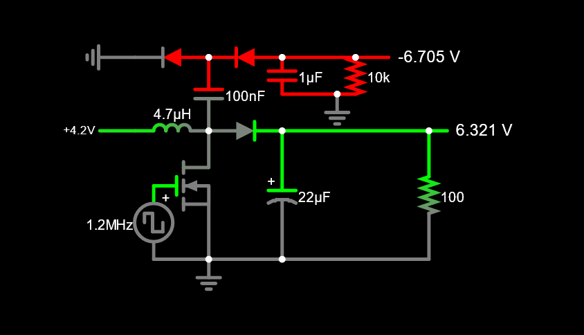
The discrete charge pump took less volume than the discrete inverter that the DSO-138 originally used. It is attached to the side of the MT3608 boost converter and wrapped with kapton tape. The overall power requirement for the device was less than 1 watt when running. Using a 5.6Wh rated battery, I get hours of runtime before needing to recharge.
I soldered a 3-pin fan header to the underside of the DSO-138 main board, this supplies the +/-7V that the LDOs on the mainboard convert. This lets the mainboard completely separate from the case.
The overall design minimized exposure of signal and power...
Read more »
 Hulk
Hulk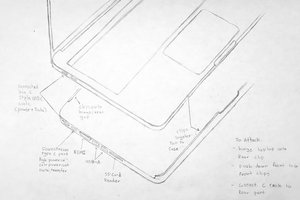
 Harrison Freedman
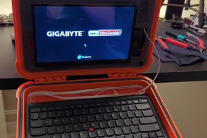
 Andrea
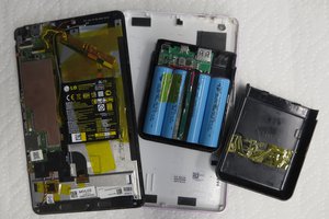
 PointyOintment