 ROFLhoff
Well since I want to drive this truck while I search for another speedometer, I better make something to take its place. I can try making a digital replacement. As mentioned before I need capture pulses to make an odometer, and keep accurate time to make a speedometer. At least that's the high-level approach.
I have an old Arduino Duemilanove that I used during my early hobbyist days. Its LDO can handle up to 20v, so it should be able to handle a bit of electrical crude. I have a spare OLED display, one of the 0.96" I2C variants. While the ATMEGA328 had better input range than other microcontrollers of the era, I will need to level shift the speed sensor pulses. A simple NPN BJT inverter with the collector on one of the input pins, and a 10k ohm resistor going from the base pin to the speed sensor signal should suffice. I'll just have to detect falling edges to update the two odometer variables.
Now I can spend the time to made a sketch and it shouldn't take much time, but I am curious how well everybody's favorite AI tool ChatGPT can do with this task. Will it make an Arduino sketch with common functions, will it focus on programming on an atmega328, manually setting up the I2C interface or use libraries?
I'm actually shocked at what it made. It used the common Arduino libraries, setup the I2C correctly, used the right OLED display library, it setup and used interrupts correctly. There was very little I had to adjust. I'm sure ChatGPT stole someone's working code, it was too good.
I have the working code included as "speedometer_v1.ino" in the project files.
Now it's one thing to just make a sketch and upload it to the Arduino, I did not want to cut the wiring harness going into my dash to get the speed sensor signal, only to have the device not work. I wanted to try this code out on something else. I actually have a second speed sensor that fits this truck. For some reason when you buy these sensors, they don't come with the actual gear that meshes with the transmission, you're supposed to keep the old one and stick it in the replacement. I wasn't going to drop the sensor on the truck so I can spin this sensor on my desk. It's a fairly deep shaft that a finger wouldn't fit in. The bottom has a weird shape to it, so I can't drop a screwdriver down and twist easily.
Okay ChatGPT has been good for me so far, let's see if it can make something custom that I can use with OpenSCAD. I have a 3D printer and plenty of PLA to use. I gave it a general description of the bottom shape, depth of shaft, and to put a wide disc on top with a finger cutout so I can twirl this new part. And ChatGPT did not disappoint.
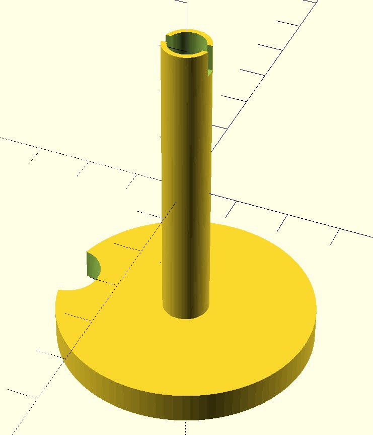
Outside of correcting the units, it gave useable code. After converting the code to STL, and generating Gcode in Ultimaker Cura, 90 minutes later I had a working part!
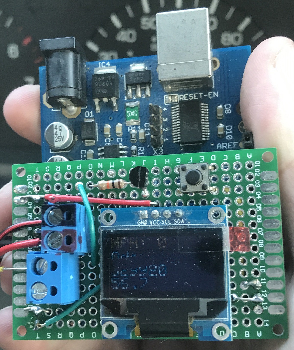
This was a satisfying picture to take!

The white breadboard has a 555 timer for testing, but in this image it's just being used for the +12V/GND access. The OLED is on the yellow breadboard, and the extra button is there to reset the trip odometer. Currently on the OLED display is the speed on the first line, the second line is fixed text, the third line is displaying pulses (that large number is the current engine mileage * 4000 pulses/mile), and the last line is the trip odometer in pulses. The final code used miles, but I did not want to spin this sensor 400 times to increment the trip odometer a tenth of a mile.
The DSO-138 oscilloscope is storing a period of pulses from me spinning the sensor for a few seconds. On the top left is says 11.415Hz, which comes out to 10.3 MPH. The OLED display is continuously updating the speed, so in the time that I'm taking the picture it's going to read 0 mph.
I included some startup code that checks if I have the trip odometer reset button held while powering the Arduino, which puts it an adjustment mode. Using the Arduino's COM port, I can update the mileage.
I'm very satisfied with the code so far, so I made a shield for the Arduino. I have three screw terminals for the power and sensor signals, a reset trip odometer button, and the display one one board.
Unfortunately the screen is not readable in daylight. While it keeps accurate mileage, it is only really visible while driving at night. The blank blurred part of the screen is due to the rolling shutter on the camera while the screen is cleared and updated.
Overall this display took me three hours to make starting from the first ChatGPT prompt, to uploading code to the Arduino, waiting 90 minutes for the printed part, a half hour to make a shield, and installing it in the truck. ChatGPT saved me so much time writing code, where all I had to do was polishing the output. 10/10 would do again.
Hopefully I can find another speedometer soon, I may get fed up and find a larger digital display to use.
Discussions
Become a Hackaday.io Member
Create an account to leave a comment. Already have an account? Log In.