 Josh
Josh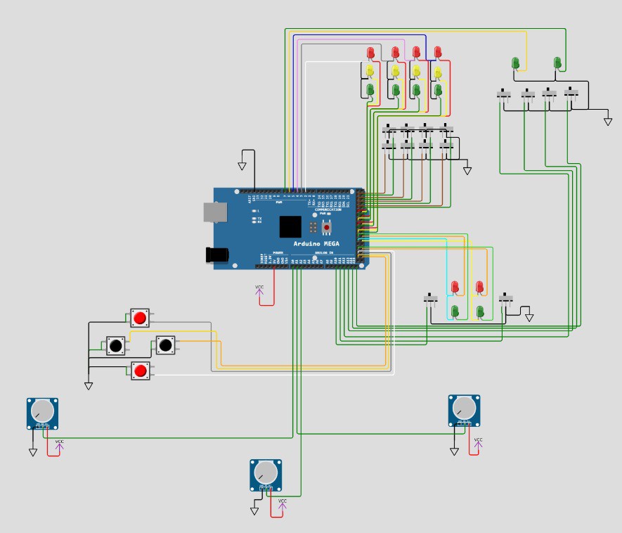
This probably doesn't make much sense, but the above image is snipped from my draft schematic over on Wokwi.com. Here's the link: https://wokwi.com/projects/370089092702920705
I have decided on a general layout for the components in the case as follows:
At the top right you can see 2 green LEDs and 4 switches. The center two switches will function as "soft" power switches to activate two main sections of the board. The switches on the left and right can then activate subsections of the board as well, or just do something with the two LEDs up top. Both LEDs are on their own PWM channel. (Obviously they can be programmed to do anything... but this is the start.)
In the top center section you can see 8 switches and 12 LEDs. This is actually representing 4 on-off-on switches, with an LED at each position next to each switch. This section allows some puzzles to be created to match the switch position, for example. (Wokwi did not have a SP3T switch so i'm simulating it with two switches and don't have time to figure out how to do it another way)
I have wired the 12 LEDs so that each triplet of LEDs associated with a switch has it's own PWM channel, as notionally I would only have one of the three LEDs on at a time and it gives more control of dimming with the hardware PWM. The PWM pin will drive the common anode connections and enable me to dim each set of 3 while turning the individual LEDs on using the Digital pins on the Cathode set to LOW. (...and I just noticed that I have all 12 of those LEDs backwards in the schematic, so on/off and PWM is reversed as pictured)
In the center below that are two SPST switches, along with a LED for each position. Again each switch pair is driven by PWM and a digital output for on/off.
The pots are a little different story. They are obviously hooked to the analog inputs, but the one in the middle is actually a 10-turn, whereas the outside ones are just standard 270ish degree turn. My plan with these is to initially control some dimming of the LEDs. Later on I want to add 2 .98" OLED displays and use the pots for game inputs.
The buttons... These are also intended to be used later for game input. I don't have LEDs for them, but I may add some. I do have several outputs left and it would make for an easy simon-says type game.... I think I'll add that next....
Discussions
Become a Hackaday.io Member
Create an account to leave a comment. Already have an account? Log In.