 Josh
JoshOnce I finish the wiring, it was time to load the code that I had written using ChatGPT and simulated on wokwi.com. After realizing I didn't have the proper drivers installed, I loaded the code and proceeded to find something wrong.... Actually only five things wrong:
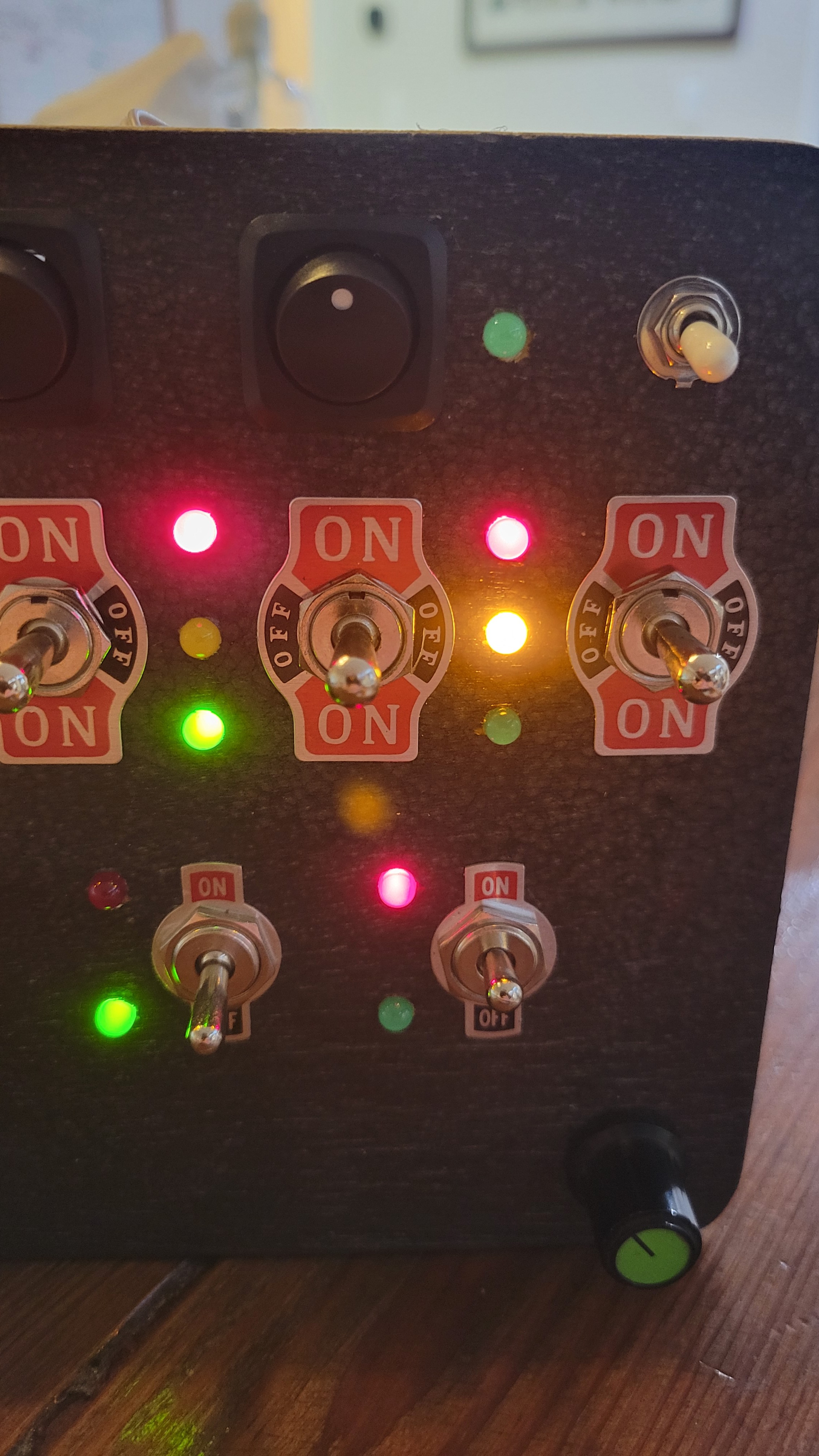
- Two of the 3-way switches had more than one LED illuminated.
- Two of the 3-way switches activated LEDs next to a different switch.
- One of the toggle switches had LEDs illuminated inverse of the other.
- The working 3-way switches had LEDs illuminating inverse to the switch.
- On the switches with more than one LED illuminated, turning the potentiometer for dimming made one LED brighter and the other dimmer.
Solutions:
- Turns out I accidentally reversed two red LEDs when I installed them. Resoldered to fix.
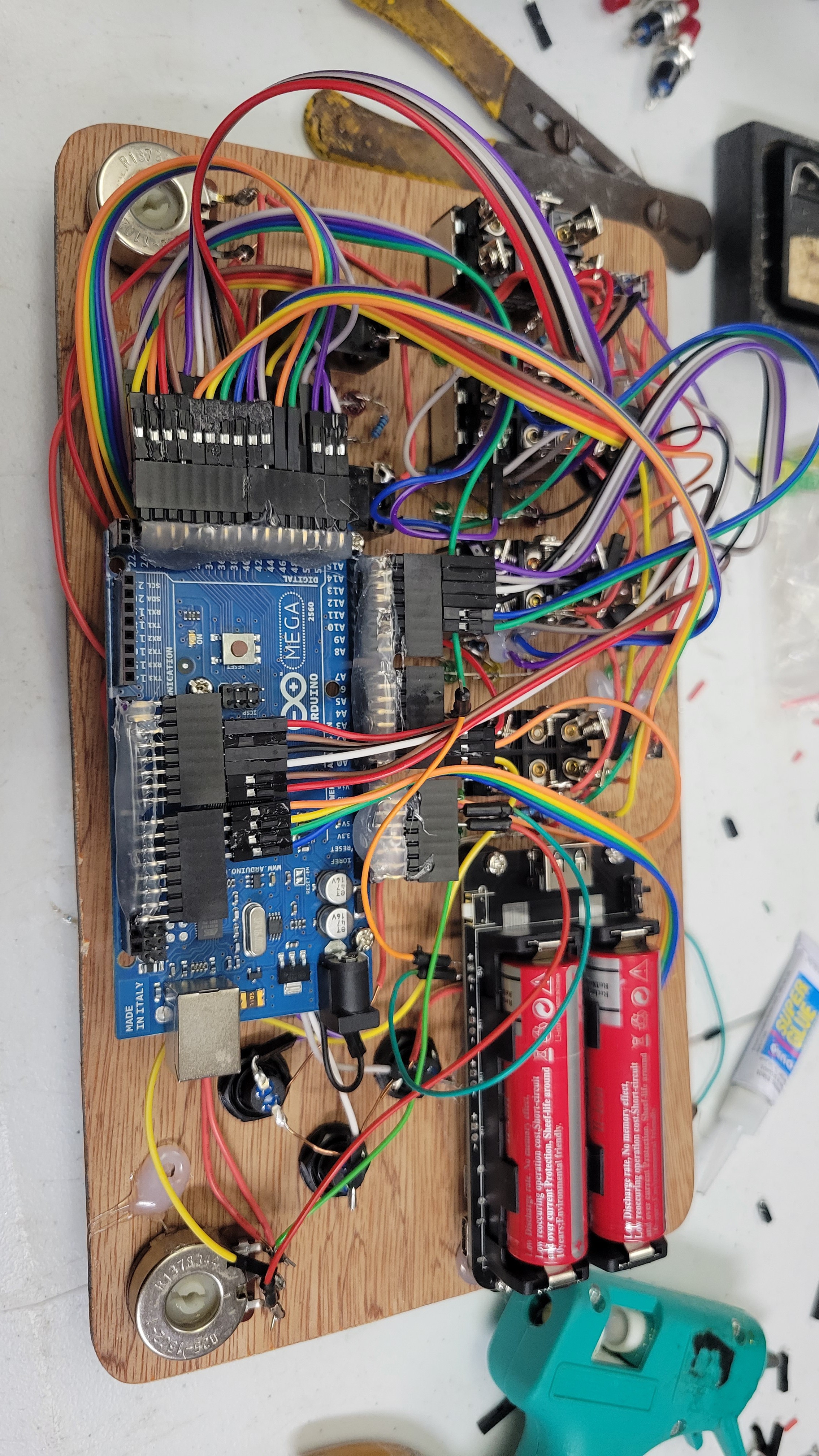
- This one was one of my switch connectors being reversed. The top of all the switches go to a single four-pin connector, same with the bottom. One of these connectors was backwards.
- This one was more complicated because when I super glued the pin connectors together to make a single connector I accidentally cross the wires for 2 LEDs. This one I fixed by swapping their pin assignments in code.
- Similar to solution (2), but I had each connector plugged into the wrong set of pins. The code thought the switches were up instead of down, and vice versa.
- This is the same as solution (1) but worth mentioning separate because I was using the digital outputs as high for off, but since the LED was backwards it was conducting back into the analog output when the PWM signal was LOW. Since the time period for low and high on PWM are inverted, when I dimmed the properly connected LED, the improperly connected LED got brighter accordingly. Cool effect but not what I was looking for...
Amazingly, after fixing all of these things which were hardware issues, the code worked exactly as I designed it! The only thing I did to the code was add some serial output in order to troubleshoot the issue with the reversed LED which actually took a little while to figure out.
I will post the code separately.
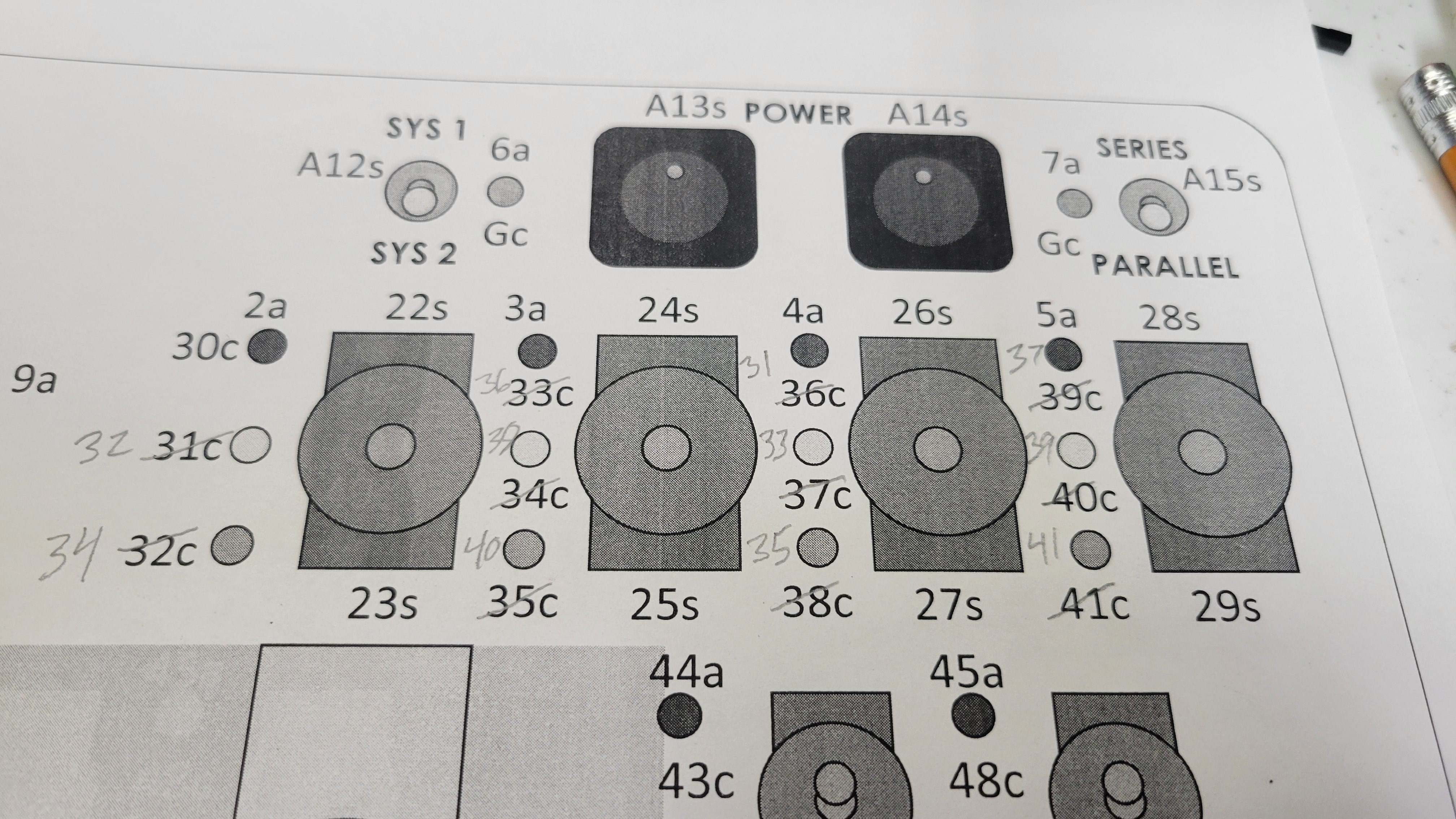
While I was putting everything together, I had a diagram that I printed out with all of the pin destinations on to help me hook it up properly. When I determined I had the wrong pin locations, I manually updated this sheet. The biggest update was actually rearranging the first six three-way switch LEDs to be on even pins and the second six to be on odd pins. Just let me plug them in to the Arduino in groups of six on my 90° makeshift pinheaders. The ribbon cables come with individual pins but I used super glue to make them into multiple-pin connectors.
Other items to note: I have been using ample amounts of hot glue in order to secure everything against the inevitable shocks and vibrations of a 2-year-old's playing.
Here are some pictures:
Discussions
Become a Hackaday.io Member
Create an account to leave a comment. Already have an account? Log In.
GPTOnline.ai est le compagnon idéal pour répondre à vos besoins. Nous offrons une riche expérience qui vous permet de vous exprimer pleinement et d’explorer les profondeurs illimitées de l’art. Avec GPTOnline.ai, vous pouvez libérer le potentiel créatif qui sommeille en vous. https://gptonline.ai/fr/
Are you sure? yes | no