 Sebastian
Generally, test and measurement equipment needs a certain period of warm-up time to reach a thermal equilibrium that allows for low thermal drift. That is also true for the programmable decade resistor. I’m especially interested in the warm-up time with all relays off as well as with many relays on. I chose a value of 100 kΩ for the latter.
(For simplicity I decided against using latching relays, however that would have been a better choice performance-wise as mentioned before. Due to the additional power dissipation in the relay coils the curves will look different.)
The programmable resistor decade mainboard has two temperature sensors that can be read remotely via SCPI. To have a more complete picture I’ll also use the SCPI thermometer (previous project, https://hackaday.io/project/190792-scpi-thermometer) to sample the ambient temperature. So let’s collect some datapoints and plot a few curves.
Input off
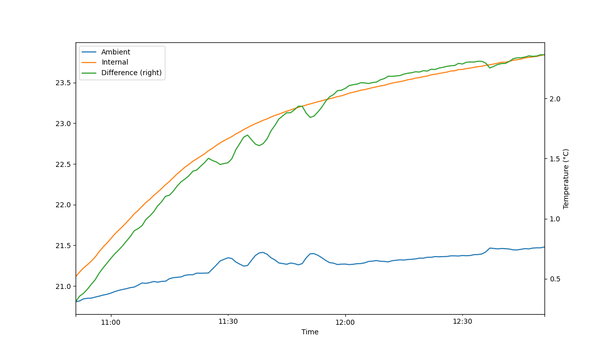
Temperature rise with all relays disabled (input off). Temperatures on the primary y-axis also in °C
Unfortunately, I had to correct a simple error in the test program so the unit was already on for a few moments, explaining parts of the gap between the internal and the ambient temperature. Also, the internal temperature sensors are not nearly as precise as the sensor used in the SCPI thermometer, so a certain deviation/offset between both sensors is expected. The temperature rise is fairly limited and it takes about one hour to see most of the temperature rise. According to the measurement it would likely take more than two hours for the unit to reach a thermal equilibrium. That being said, the steadily rising ambient temperature limits my confidence in the measurement, but hey, it's good enough.
Note: The small (positive) temperature peaks likely came from the laptop fan that switched on intermittently, although the ambient temp sensor was about 1 m away from the laptop and not (directly) in the airflow. Also, I did the measurement on a day with significant solar radiation that heated up the room.
Input on
I tried to optimize the measurement protocol for the second more interestingly scenario with 100 kΩ at the input (only partially successful, I guess). Here it is:
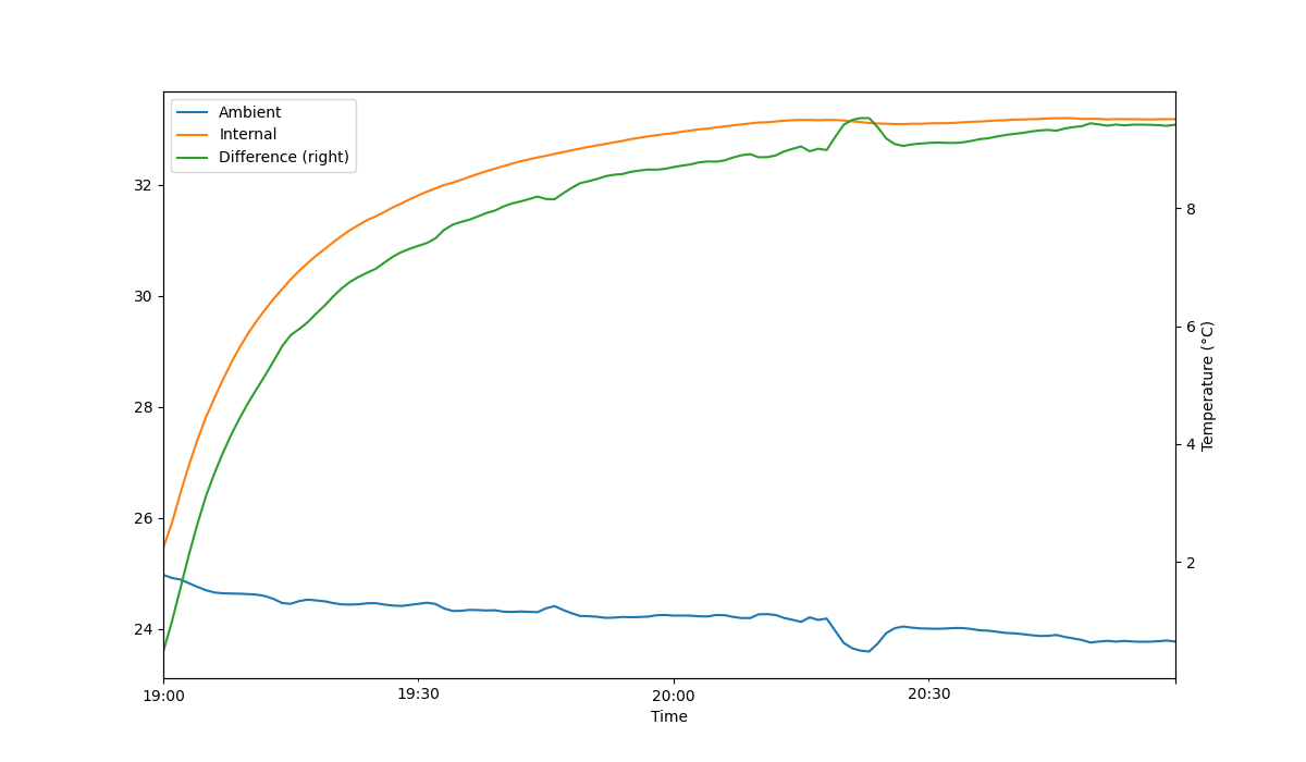
Temperature rise with input enabled and set to 100 kΩ. Temperatures on the primary y-axis also in °C
As expected the power dissipation of the relays and the power supply, 2 W or thereabouts, increases the internal temperature significantly. Compared with the previous scenario, the final temperature increase has roughly trippled, and is now at about 8°C. After 30 min, the internal temperature rise is already at ~80% of and after one hour effectively at the final temperature. The dip in the ambient temperature was likely caused by temporarily opening a door.
Next steps
My conclusion is: Wait at least 1 hour with the input enabled and at something like 10 or 100 kΩ before going through the calibration procedure. And this is what we'll do in the next log.
Discussions
Become a Hackaday.io Member
Create an account to leave a comment. Already have an account? Log In.