 Sebastian
I went into this project with the thought that it will be a rather small one. This certainly influenced some decisions I made along the way. Now that the project had evolved into a much larger thing than initially anticipated it’s reasonable to have another look at possible optimizations, albiet the calibration results were already pretty satifactory. A small modification - seen in the following picture - can make quite a difference, so why not do it?
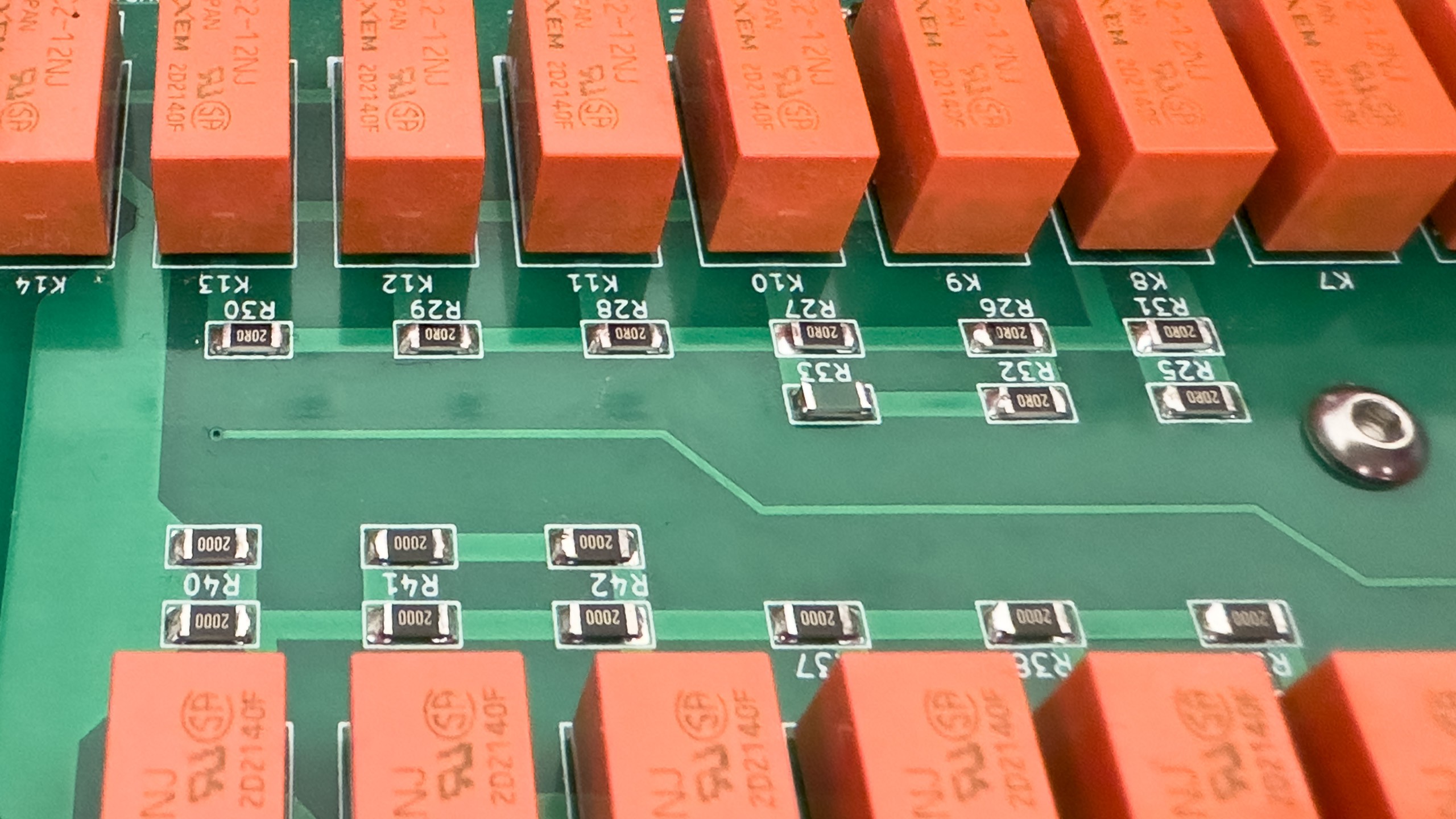
A green 20 kΩ resistor soldered on top of the 20 Ω resistor in order to improve accuracy for low resistance values. Note the similarities of the PCB layout and the second schematic shown below.
The contact resistance again
From the start it was clear that the relays’ contact resistances will reduce the accuracy of the programmable decade resistor, especially in the lower two decades.
To mitigate this issue I used high quality relays and paralleled their two poles. To further improve accuracy I added bypass relays for the lower three decades that bypass effectively shorted higher decades. What I did not
do though: Adding footprints to improve accuracy by measuring the actual resistance and connect a matching resistor in parallel to the "main" resistors. Again, this was intentional to reduce complexity and the required board space. Also, the contact resistance is not constant, so there will always be some deviation caused by the relays. And with the topology I selected it’s not quite so easy to compensate for the contact resistances, because the contact resistance varies between odd and even resistance values. These problems are a byproduct of reducing the number of relays required.
And of course, shorted decades (nominal resistance of 0 Ω) will always have a residual resistance, bypass relays present or not. Shall we compensate for those as well to get better accuracy for the lower decades at the cost of the higher decades where the bypass relays are not available? One could argue that it would be preferable to do so, because a few milliohms do not matter for larger values.
Solutions
That being said, improvements can be achieved even if the result will be far from perfect even after the optimization. Let’s take a look at the schematic of the first decade:
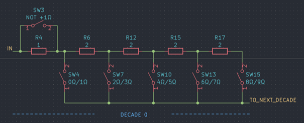
Simplified decade resistor topology
There are two variants I’d like to discuss that improve the situation:
- Variant 1: We connect resistors in parallel with R4 and R6 respectively that reduce each resistance by about one relay’s contact resistance (as per calibration results about 25 mΩ).
- Variant 2: We only use one resistor, parallel to R6, so that the resistance is reduced by two times the contact resistance (50 mΩ)
| Nominal resistance (Ω) | Relays in signal path | Contact resistance (ca.) (Ω) | Expected offset with variant 1 (ca.) (Ω) | Expected offset with variant 2 (ca.) (Ω) |
|---|---|---|---|---|
| 0 | SW3, SW4, bypass relays | 0.075 | 0.075 | 0.075 |
| 1 | SW4, bypass relay | 0.050 | 0.025 | 0.050 |
| 2; 4; 6; 8 | SW3 and (SW7 or SW10 or SW13 or SW15) and bypass relay | 0.075 | 0.050 | 0.025 |
| 3; 5; 7; 9 | (SW7 or SW10 or SW13 or SW15) and bypass relay | 0.050 | 0.000 | 0.000 |
We can clearly see that both solutions are not perfect. I prefer variant 2, because this improves the situation significantly for all resistance values greater than 1. In contrast, with variant 1 we have a large offset of about two times the contact resistance for all even values, whereas for odd values we have reduced the offset to ~0: The error varies significantly between consecutive resistance values.
But how would we calculate the resistance required for variant 2? The calculation is very simple. With Rp as the resistance of a parallel connection and Rp1 and Rp2 as the branch resistances we get:
Let's say we want to decrease R6 by 50 mΩ, then we calculate the value of the resistor Rp1 to be connected in parallel as follows:
![]() Implementation
Implementation
In reality, we used 4 resistors (R7 - R10) in place of R6 from the schematic above. This leaves quite some options to implement the parallel connection.
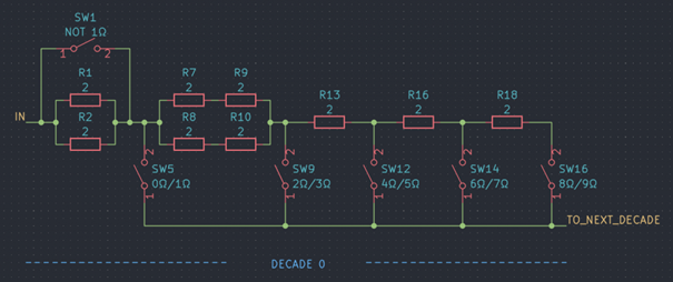
Actual topology
Every decade uses nine resistor of the same value. In order to get a bulk discount I ordered ten for each decade, so I have one left. I wonder whether I can use the tenth resistors here. Sure enough: I would simply solder the tenth 20 Ω resistor in parallel with one of the resistors R7 – R10 (doesn't matter which). This will reduce the resistance by about 46.4 mΩ. Since there is no exact value for the contact resistance anyway, this should be good enough. (By the way: The thermal coefficient of the ten times larger resistance connected in parallel isn’t all that critical – a ten times larger thermal coefficient of 100 ppm, compared to the 10 ppm of the precision resistors, shouldn’t degrade the overall performance significantly, so a 100ppm 22 Ω would do fine). And for the second decade we could simply use the 2 kΩ resistor to reduce the 20 Ω nominal resistance by about 49.6 mΩ.
And this is what I did and what can be seen in the picture above: A green 20 kΩ resistor on top of a 20 Ω resistor (second decade).
Next steps
With this modification done it's time for the final calibration.
Discussions
Become a Hackaday.io Member
Create an account to leave a comment. Already have an account? Log In.