 Sebastian
I was asked a few times how I did the front and rear panels, so this is what I’d like to talk about in this blog. There are different ways to achieve a similar result. For me, the easiest and most cost-effective solution was to just design another PCB – I know how KiCAD works and it does everything I need it to do.
The basics
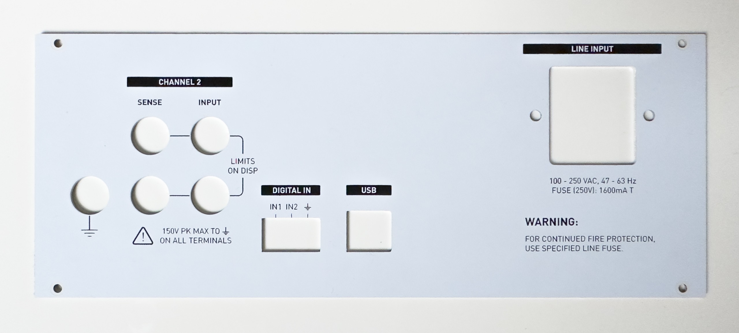
Depending on the actual use case you can use a regular FR-4 board. For this project, however, I chose an aluminum PCB. Those only have one copper layer and the prototyping service might (and probably will) specify different limits/process parameters. But other than that it is very similar to designing a regular PCB.
The first question might be which side of the PCB shall be visible. For this I chose the top side, i. e. the side where the copper layer would be. This allows me to remove the solder mask from the bottom, exposing the bare aluminum (again: This is a one layer PCB). Now the aluminum part makes good electrical contact with the case, so that it can be grounded properly (safety) and work as a shield.
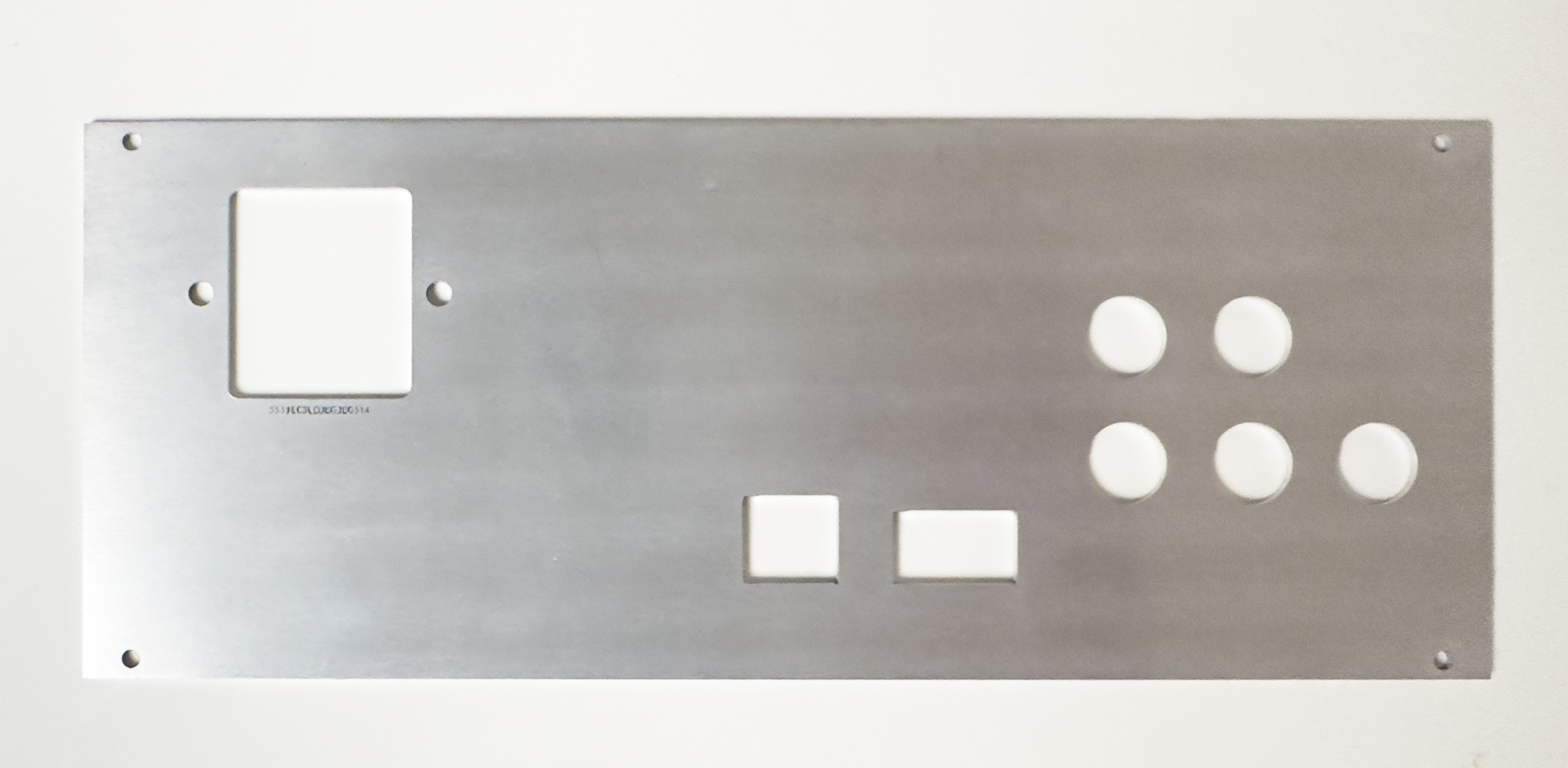
Then I removed the copper layer (almost) completely, because I didn’t want to risk having a large floating conductor anywhere*. The solder mask, however, stays in place, giving the front panel its white color. The (black) silk screen is perfectly suitable to group and label the controls, connectors etc. In theory you could remove the solder mask partially on the front panel as well, exposing the aluminum to give you a fourth color. If you decide not to completely remove the copper, but expose it instead, you have the option for a fifth color. Whether this is a good idea is up to you.
*) At this point it probably wouldn’t really matter which side you use for the solder mask and silk screen I think
A few tips
If you plan to use certain components over and over again, maybe for different projects or maybe just because you have 20 switches of the same type on your UI board, it might be really handy to create a footprint for the cutout, labels, graphics etc. The same is also true for the outline of the panel itself. Most of my projects use the same cases, switches, power connectors etc. over and over again – so creating the footprints is what I did.
In some use cases you might find helpful to place symbols on a schematic and import the footprints based on the schematic. In most cases this would be overkill though – simply adding the footprints to the PCB (in Pcbnew) does the job equally well.
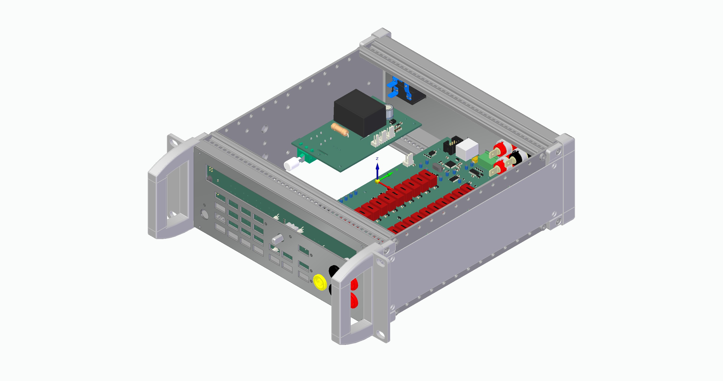
Many case and component manufacturers provide 3D models on their websites that can be combined into an assembly with all the panels and PCBs to catch errors early on. Unfortunately, there is no 3D model available for the switches I used and I couldn’t be bothered to create them myself. Still, this approach helped me to avoid some issues with the front panel that would have required a second revision otherwise – now the first revisions of both the front and rear panels worked perfectly.
The design
The layout of the user interface etc. depends on the application and is completely up to you – obviously. The labeling, the fonts, additional graphics and so on can improve or hurt the usability significantly. So it’s usually a good idea to spend quite a bit of time thinking about how you and more importantly any other operator should or would likely use the device and make it as easy to work with as possible. It can be helpful to go through a few iteration on paper (or any suitable program) before even starting the implementation in your PCB software.
Also it’s really helpful to take some inspiration from the designs of big TME manufacturers like HP/Agilent/Keysight, Keithley, Tektronix & co. You don’t have to copy them, but adopting some of the general concepts they use might get you started more quickly and may result in a more professionally look and feel.
Discussions
Become a Hackaday.io Member
Create an account to leave a comment. Already have an account? Log In.