 Jeroen Delcour
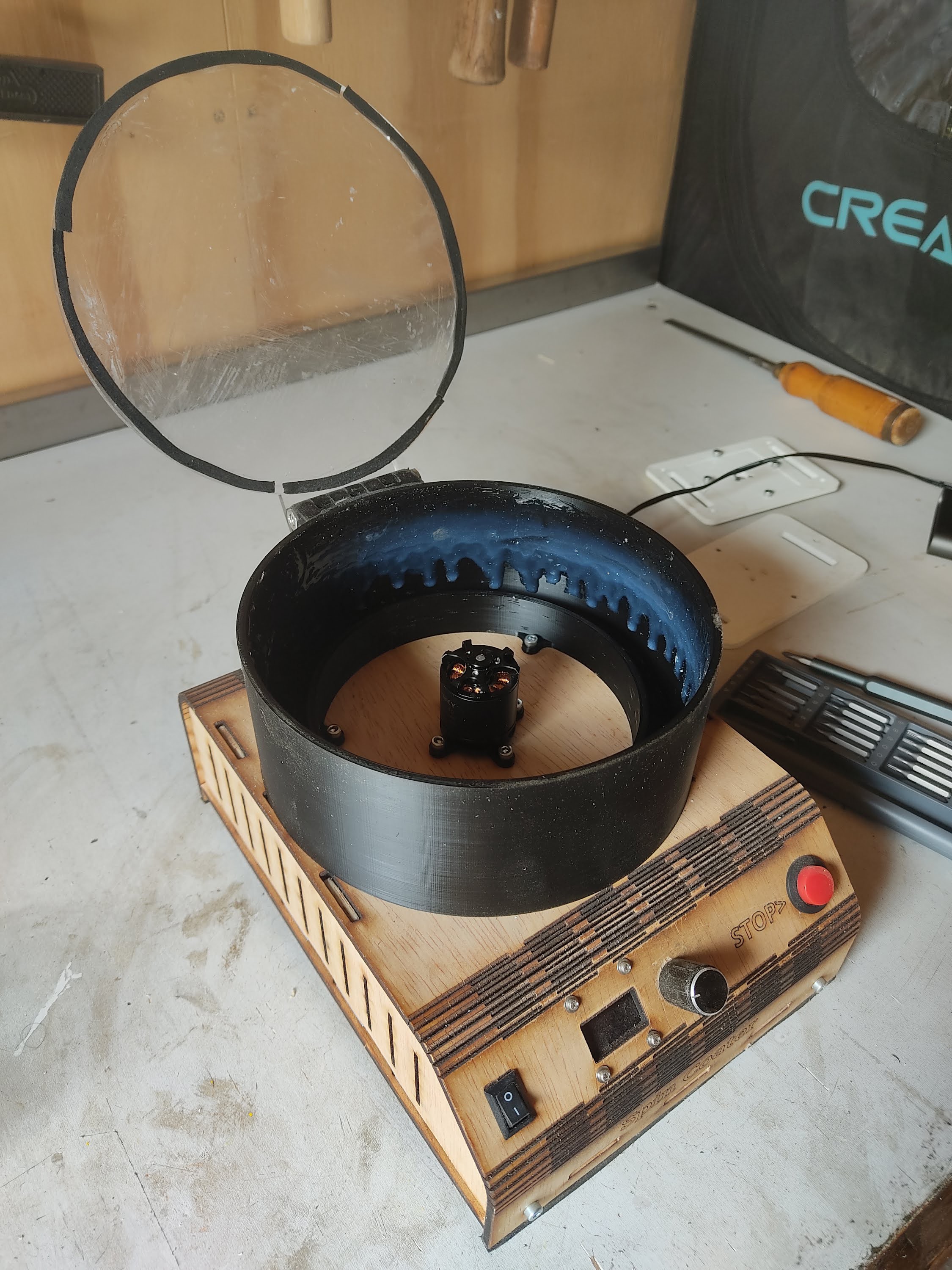
To finish up the build, I 3D printed a plate with screw holes to attach it to the brushless motor and more screw holes to clamp down a PCB. I also 3D printed a cylinder to surround the spinny bits and laser cut a lid from acrylic. The cylinder also contains a moat to collect any excess fluid that drips down the sides. I used a piece of acrylic someone left on the scrap pile at my local hacker space. I think it's been there for a long time, because the protective foil did not want to come off cleanly. In my impatience, I ended up scratching the acrylic quite a lot.
As a first test, I mixed pourable silicone rubber and put some of it on the middle of a flat PCB. This is very viscous stuff (shore 40), so I was curious to see how thin and evenly distributed it was going to end up after spinning.
Before and after:
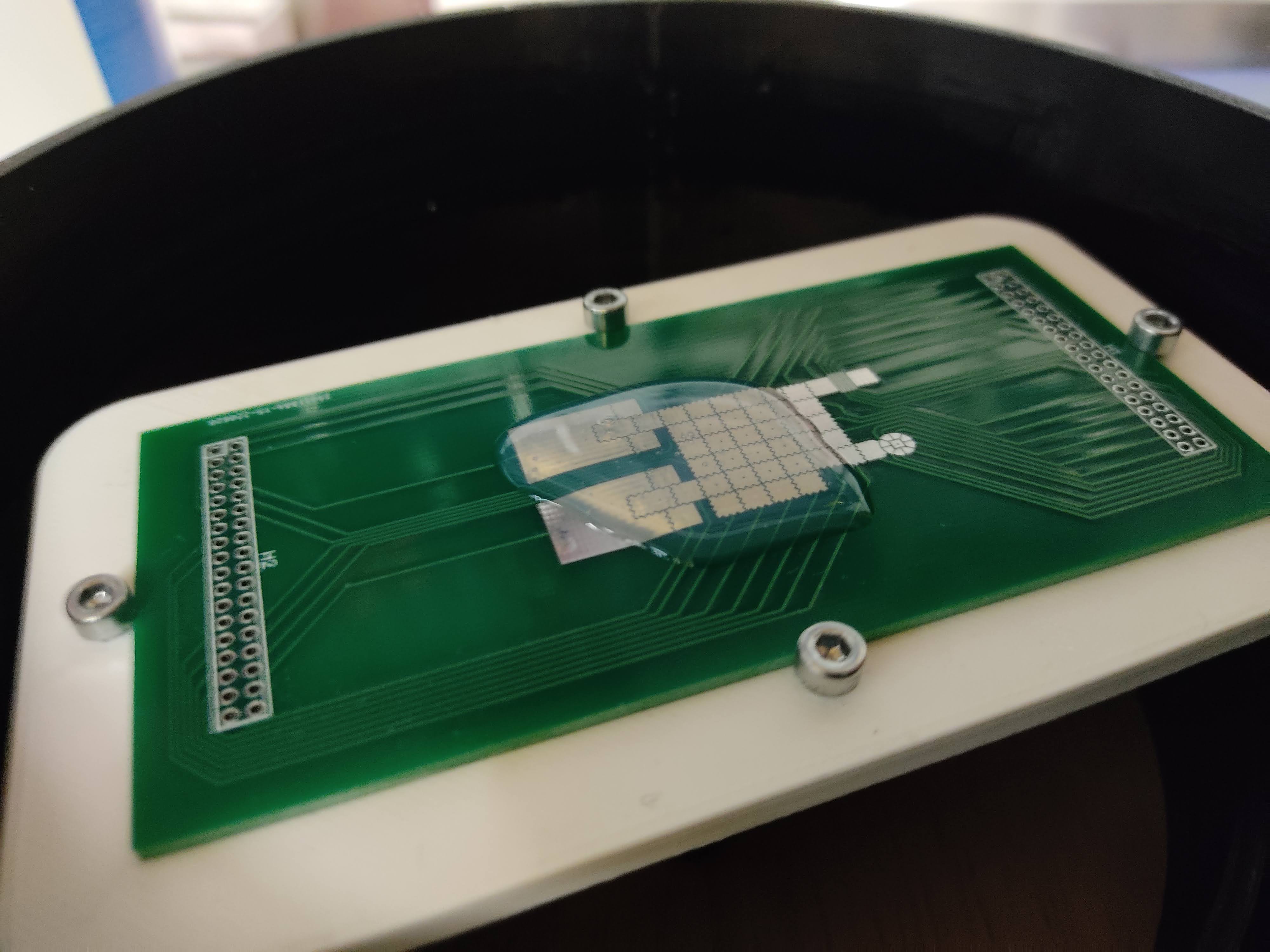
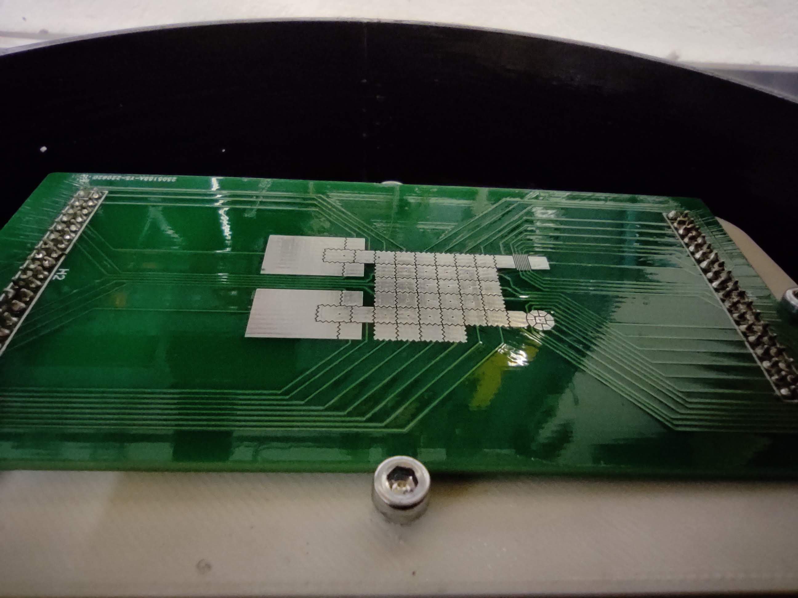
A great success!
According to the theory, the thickness of the liquid layer should be proportional to the inverse of the square root of the spin speed. I wish I had a way to measure the thickness. Maybe someday I'll build a spectroscope setup and use interferometry to measure thickness down to the nanometer range, like in this awesome video by Sam Zeloof. I wonder how affordable a white light interferometry setup would be.
After I recorded the video, I 3D printed a hinge to keep the lid in place. I also added foam padding around the rim and to the underside of the enclosure to dampen the vibrations. Now I don't have to hold it down anymore when it's running at 10000 RPM :) I also noticed the white plate I printed to hold the PCB was a bit warped, making it unbalanced. I printed another one that turned out better. This reduced the vibrations quite a lot.
You might've noticed in the video that the screens acts glitchy and the ESC startup sounds play. It seems that setting the throttle to 0 on the ESC doesn't let it spin down but actively brakes the motor. This create a spike in the power circuit that can sometimes reset the microcontroller. This is bad and can eventually break some components. I don't need active breaking, so I should really figure out a way to let it spin down freely. Or at least slowly ramp down the target RPM or something. [EDIT: Thanks to @Mathieu Lacage for letting me know this can be done using this BLheli configurator tool]
This thing has quite a lot of power! I can feel wind coming out from small gaps in the foam padding around the lid. I guess I shouldn't be surprised, given I'm using a motor that was designed to be used in a quadcopter.
The picture below was taken quite a bit later, after I got into woodworking. That's why it's covered in sawdust.
If I were to make a version 2, I'd tidy up the electronics and make the whole thing a lot smaller. Maybe add some weight to dampen the vibrations further. I'd also remove the red stop button that's not actually connected to anything (I ended up just using the rotary knob as an emergency stop button). For now, this version is actually working great and fits my needs. Hurray for the DIY community!
Discussions
Become a Hackaday.io Member
Create an account to leave a comment. Already have an account? Log In.