 Lasith Ishan
Methodology
Step 1 : Powering the motor
The configuration to power the motor is shown below. In order for the motor to move the gate in the forward(close) direction, the Main winding should be connected to the main’s power.
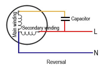
In order for the motor to move in the opposite(open) direction, the Secondary winding should be connected to the main’s power.
It is necessary to identify which wire corresponds to which winding. Usually the wires are not labelled and this can be identified with trial and error by supplying AC power to the wire.
In my case, I was working with a 220~240VAC motor. I was able to identify the Neutral wire easily as it was blue in color which is a standard color used to indicate the Neutral terminal.
Next, I connected the Live terminal to the red wire, which made the motor turn in the forward direction. This indicated that I supplied power to Main Winding of the Motor.
Note: Make sure that the starter capacitor is connected properly and functioning. This ensures that the motor has adequate starting torque.
Wiring diagram to close the gate (motor moving forward)

Wiring diagram to open the gate (Reversing the motor)
Step 2 : Stopping the motor
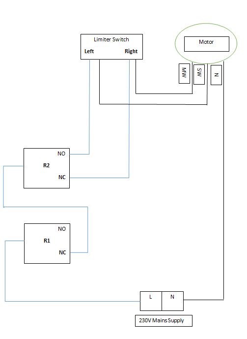
The mains power is provided to the motor through a limiter switch. As soon as the gate reaches one end the limiter switch is triggered which opens the circuit and stops the main’s from supplying power to the motor.
Step 3 : Using relays to control the motor
The relay has two contact points; Normally open and Normally closed.
The Normally closed path is used to power the Main winding of the motor. This was chosen to ensure that when the system was reset or if something went wrong in the system, the motor would ensure that the gate was kept closed at all times.
The Normally open path is used to power the Secondary winding of the motor. The normally open path is closed when the coil inside the relay is energized. This can be done by sending a 5V signal from the Arduino as the relays used are operating under 5V.
By using two paths to power the motor ensures that power is not provided simultaneously to the Main and Secondary windings of the motor.
This Relay(R2) is operated through pin 8 of the Arduino.
A second relay(R1) is used to break the circuit in order for the motor to stop if the Arduino receives the command from the receiver while the gate is moving.
The Arduino constantly checks the receiver if it has received any command. Once a command is issued the Arduino reroutes power to the motor in order for it to close or open the gate.
The main purpose of the second relay is to give the system enough time to reroute the system to power the motor without instantly changing the direction at which the motor is turning. Once the rerouting is complete the relay switches off and power is supplied to the motor to turn in the opposite direction.
This Relay is operated through pin 9 of the Arduino.
Purpose of the Second Relay
If the system is halfway through closing the gate and receives the command from the receiver to open the gate, the relay is activated to reroute power to the secondary winding. Since this happens almost instantaneously the relay is under constant pressure from the reverse voltage generated by the motor due to sudden seize of power onto the main winding. Furthermore, damaging the contacts of the relay permanently if continuously stressed.
With the help of an additional relay the power supply is disconnected to the motor and gives the system a time of 10 seconds to reroute power to the necessary windings. This reduces the stress on the contacts of the relay and increasing their lifetime.
Overview of the wiring of the system
Relay protection method:
Suppression Capacitors
When a DC motor is suddenly stopped a negative current loop is created by the coil of the motor, this is due to the inductive properties of a coil. However this can be neutralized by installing a feedback diode to provide a path for the negative current to flow.
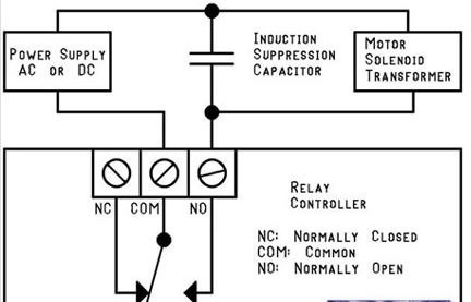
When an AC motor is suddenly stopped through a switch it creates a high voltage build up on the switch contacts.
Suppression capacitors are used to prevent the high voltage build up on the relay contacts when the motor is told to operate in the opposite direction. This protects the relay contacts.
Wiring to implement a supression capacitor
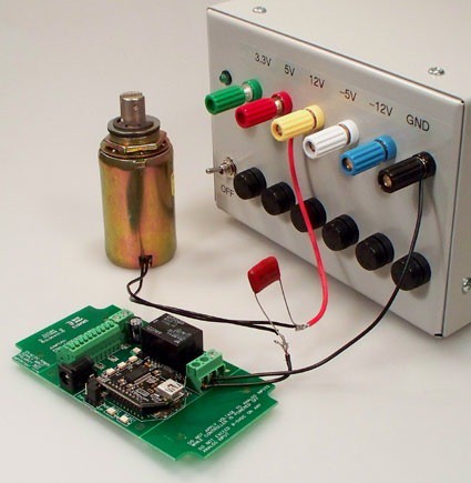
Sample image of a use of suppression capacitor
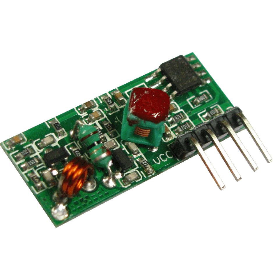
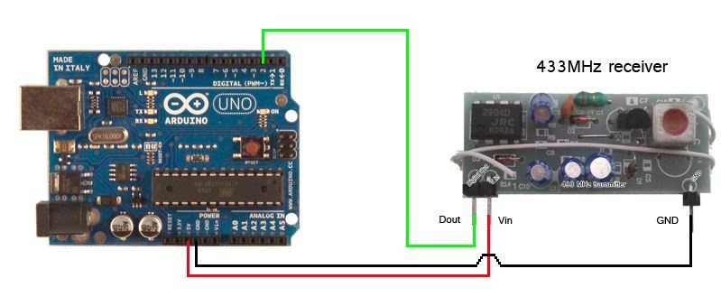
Step 4 : To configure the receiver
The receiver operates at 433 MHz, Arduino’s program is continuously looped to check the receiver’s signal port. Once the correct signal is received, Arduino then activates Relay 1(R1) in order for Relay 2(R2) to route power to the motor.
When data is sent from the transmitter it is received by the receiver in the form of an integer. In my case, using the serial monitor of the Arduino I was able to see the value the receiver was able to pick up.
The main reasons for using a higher radio frequency for communication is that the operating range is high and the signal is received by the receiver even if there are a few obstacles blocking the signal. This can only be achieved by high frequency radio waves.
In my project I was able to get a working radius of about 30ft for the system to activate.
Note: The functioning radius of the system can be expanded by a few feet by soldering a long length of wire to the Antenna port in the receiver module.
433Mhz 2 channel transmitter

433Mhz receiver
Sample receiver wiring diagram for Arduino
 Demo Video