 Paul McClay
update: added next rev pix & notes at end
Just a "quick" note about cable management because I'm thinking about it while iterating the 3d printed parts design to print a set that doesn't require artisanal handcrufting to finish.
Wires around moving parts need help to stay out of trouble:

Easy answer: Big stiff loops that can't fit into small places help. And that works fine in a big or open frame with lots of room for (relatively) big stiff loops to move around. If you're just here for the CNC mechanics and don't care about compacting the whole works, then you get the easy button.
But I want more smallness; Crowding the moving wires into less space, without binging complexity, is less easy. Between this project and its laser-cut precursor, I've spun several variations of this basic mechanical configuration and still don't really have cable management solved. Here's the latest XY stage -- the thing I should be iterating into obsolescence instead of rambling here...

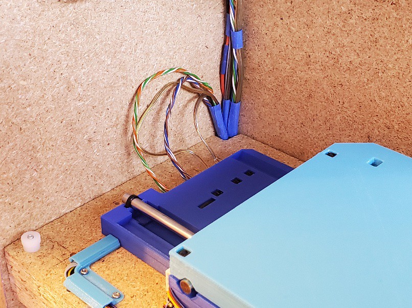
The folded bundle of wires between the fixed base and lower stage cycles back and forth in a vertical plane pretty close alongside the side without getting into trouble. Breaking the 2d motion of the upper stage into two 1d motions keeps the upper part similarly simple while the lower part is just a few more wires in the bundle that's already there.
The visible wires feed the motors. The limit switches and their cables are internal, which was an aspiration that came along with the freedom of 3d printing to make parts busy on the inside.
In that (currently current latest) iteration I wanted to include connectors to disconnect above the deck without pulling any wire up from the lower compartment, and include some provision for managing excess wire within the footprint of the XY stage. Because wires won't be exactly the correct length, and can't be too short, so they will be too long. Especially while "correct length" keeps changing. That makes it much easier to remove/replace the XY stage for whatever reason. I like the functional benefit but that version isn't the answer. Next rev is printing while I'm typing here.
I had convinced myself to stop thinking about wiring the motors internally because that wasn't going to happen without ditching the (relatively) bulky connector on (some of) these motors. My current thinking is that adapting the design to the motor wires & connectors will net-simplify construction vs requiring to mess with the received motor wiring.
(aside: That may change. Especially because there are two flavors of the motor I'm using and differences include the length & termination of wires -- and I just received a 'type A' motor with 'type B' wire length and connector so "be sure to order type A" might fail to make the received wiring predictable.
...now returning to the previous digression...)
The Point
...of this log entry was to note that, while (distracted from) iterating the 3d printed parts to print a set that doesn't require artisanal artishandcrufting to finish, I think I accidentally figured out how route the motor wires internally. That could be très slick, enable a little more compactness of frame footprint, and get more working parts out of the milling debris field. But I really have to not go down that rabbit hole right now. But I don't not consider it anymore.
the update:
The next rev
I really liked how that (above) worked out functionally -- and also noted a bunch of flaws, and reconsidered some deferred questions.
No artisanal handcrufting required:
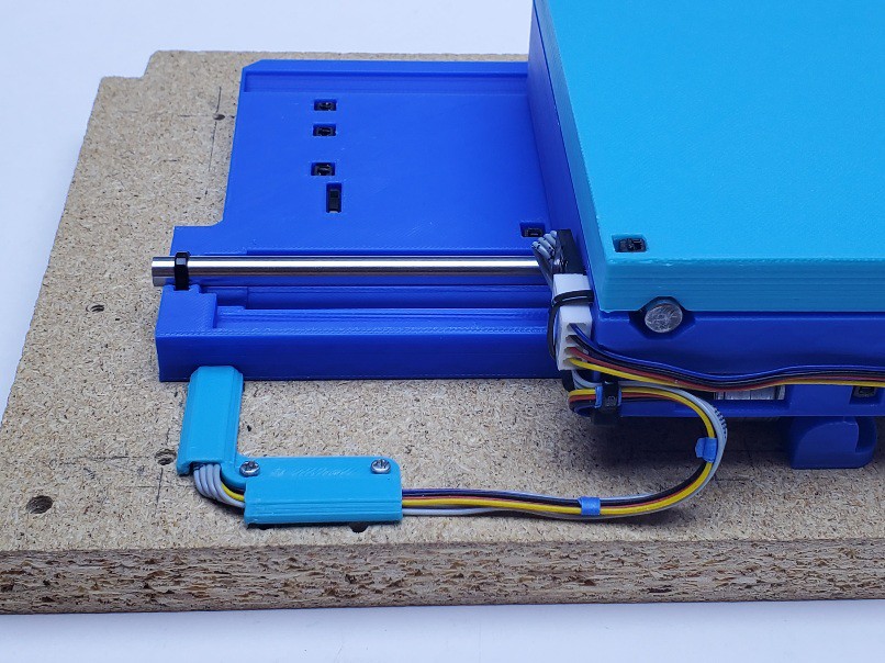
A couple bits of tape make life easier when the unit isn't bolted down to a surface.
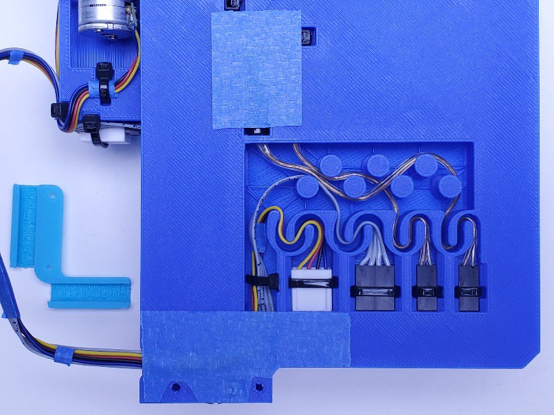
Using "serpentine" strain reliefs for a relatively gentle hold on the cables to answer expectation that they will actually get pulled on -- because nothing holds the DuPont-like housings from sliding out (they're blocked from pushing in). Funny that I made the motor cable channels bigger then put thinner cables in them.
Hmm - the serpentine behind the white connector is superfluous. I guess it's there because this arrangement had to fit 4x DuPont connectors first, then modified for the different housing
While the buttoned-down look is nice, the real motivation for the little outrigger wire guide is to establish where the moving cables attach to the deck without having to measure and mark. If you like this cable dress from the motors to the deck but don't want to fuss with leading the cables through the base, you can just use the guide to mark the deck and the wires for where to anchor the wires on the deck, then ̶ ̶c̶h̶u̶c̶k̶ ̶i̶t̶ ̶ send it to your favorite PLA reprocessor.
Discussions
Become a Hackaday.io Member
Create an account to leave a comment. Already have an account? Log In.
If you want to simplify the wiring then the best way to do this is to switch to a bus based communications method and put a cheap MCU/motor driver right by each motor. I would suggest using the LIN bus (a single wire) and adding an interrupt line for the limit switches. This would reduce the number of lines to just four (two power, one bus, one interrupt) and also enable you to a single low pin count flexible cable (like this https://www.digikey.com/en/products/detail/te-connectivity-amp-connectors/A9AAT-0505E/470342 ) to connect each axis.
Are you sure? yes | no
Hi Gravis. Thanks for that link! Solder tabbed flat flex cable looks like *exactly* what I didn't know the name of to find for another project.
I get the concept of bus connected motor drivers but I don't know anything about real available parts. In a quick bit of reading I didn't find any drivers that aren't 10x-100x out of scale for cost and physical size. Any suggestions for cheap and small drivers?
Are you sure? yes | no
here are options based on the amount of power required:
* 1A: https://www.digikey.com/en/products/detail/allegro-microsystems/A3916GESTR-T/6348448
* 2A: https://www.digikey.com/en/products/detail/toshiba-semiconductor-and-storage/TC78H670FTG-EL/11568779
Digikey calls these motor drivers a "Driver - Fully Integrated, Control and Power Stage" as you can hook motors directly to them.
I've reconsidered my suggestion and a small MCU by the first motor driver would remove the need for a common bus. Instead the MCU (with 13 or more IOs) has four GPIOs connected to each motor driver (8 GPIOs total), limit switches wires, and then a two wire communication bus (e.g. UART) with an interrupt line.
It looks like an cheap ATTINY406 can handle the job though some people aren't keen on using low resource chips like this.
Are you sure? yes | no
Ah, you were thinking of a board(s) design/build project from bare chips. I suppose there's a fair chance that could fit in the available volume. Sounds like a great project for someone with significant motivation to route marginally fewer wires. ¯\_(ツ)_/¯
edit: if messing with stepper drivers, I'd first want to try a low-voltage option like Pololu's DRV8834 or STSPIN220 modules to see if they do better at sensing small currents and matching between coils for small motors.
Are you sure? yes | no