 Paul McClay
<update today=2024Mar23: link to Discord server</update>
This is a draft in progress, but if you want an early start here's something to start with. There is a lot of me describing what I do rather than saying what you should do because this is just the beginning of letting daylight into the path-dependent evolution of how I've been doing this, and of the "this" that I thought I was doing. Some stuff may be mid-edit nonsense. Or pre-proofread nonsense. Public chat is open for the project -- big orange button on the project page. Also a Discord server. So far the Discord has more traffic.
Build yer X-Y table/stage/thing
part checks & cleanup
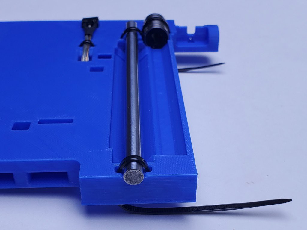
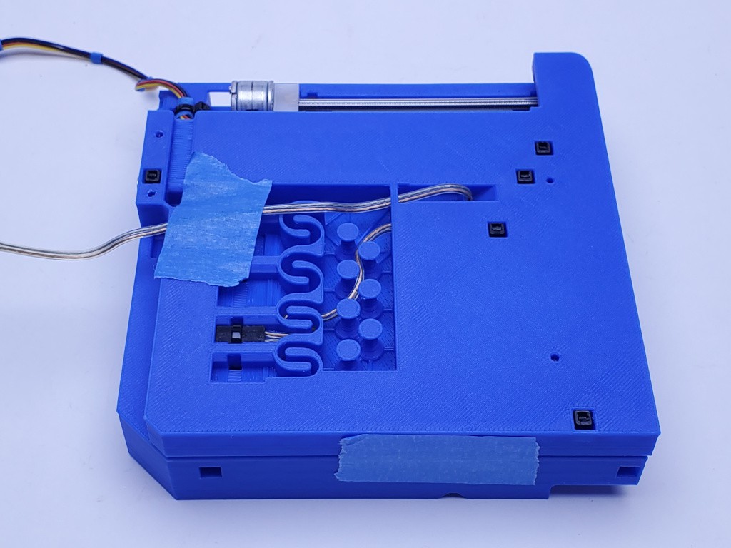
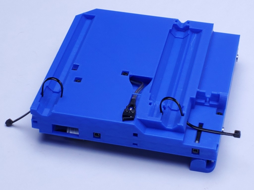
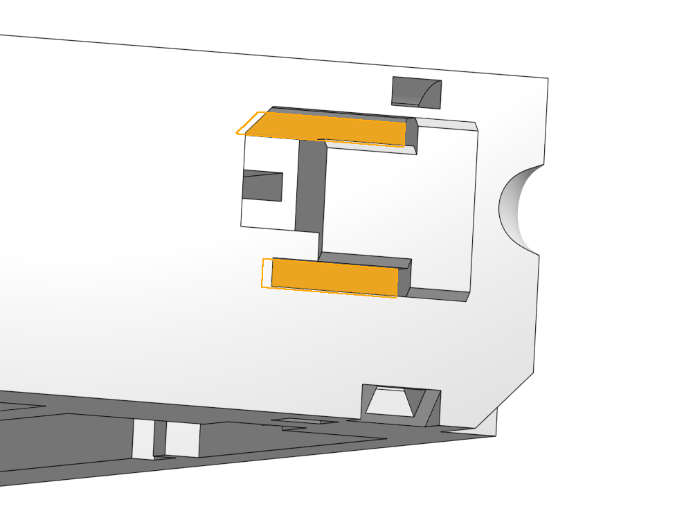
Check all the V-block surfaces -- the 45º flats within zip tie circuits. See bright blue highlights in the image below. Low spots are probably ok but high spots are trouble.
Check some of the vertical flat surfaces, and probably trim some edges. See the yellow highlights in the image below. They include the inboard ends of the bearing V-blocks and both ends of bearing clearances. The outboard ends of the bearing V-blocks need to be clean enough to allow the bearings to sit level in the blocks but are not dimensionally relevant. Also the perimeter end of the motor bay and the business end of the limit switch clearance. These surfaces should be flat and perpendicular to the top or bottom of the part. but likely have some distortion due to elephant's foot, top solid layer expansion or some such, and likely need a little trimming where the vertical meets the top/bottom face of the part.
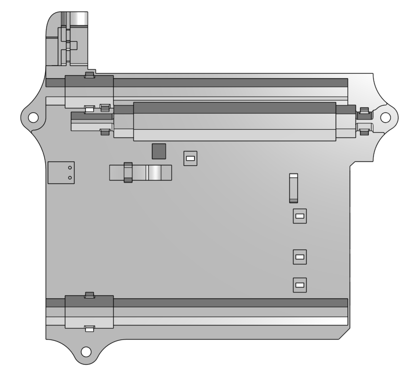
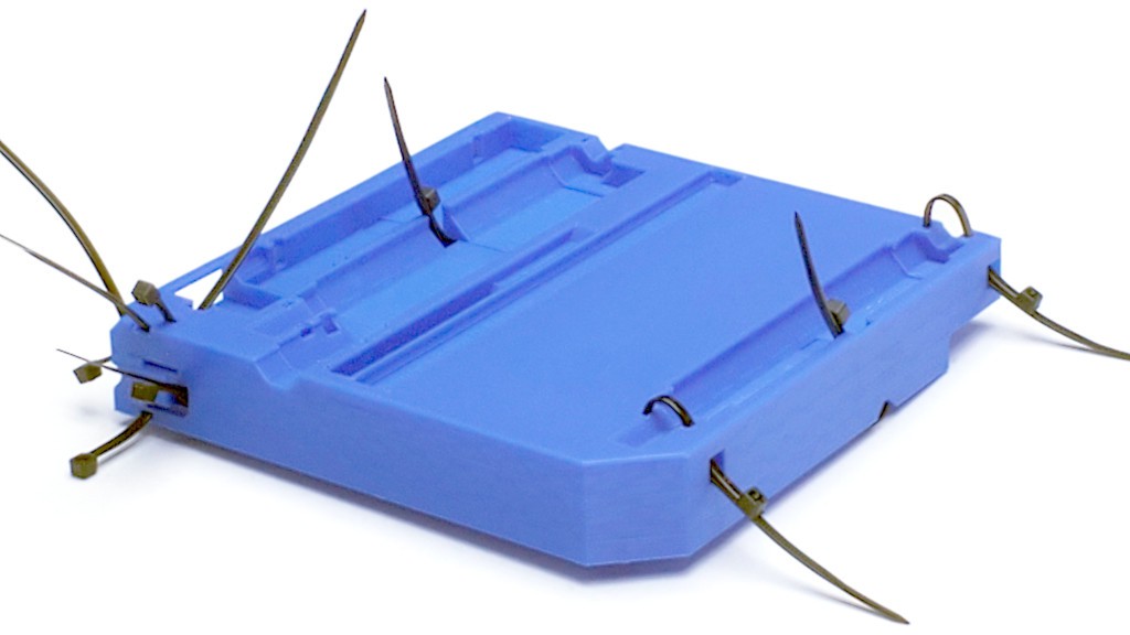
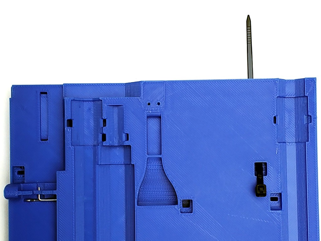
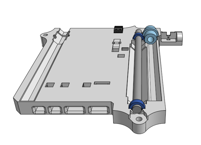
note: the bottom part you printed from the STLs uploaded here will have three attachment tabs around the edge that are not shown in the photos here (and fewer holes on the bottom)
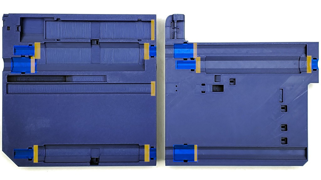
Here's what the bottom part uploaded here looks more like:
The low locating feature at the other end of the motor bay needs to be clean too, but it always has been in my experience.
Generally clean up stuff that doesn't look right.
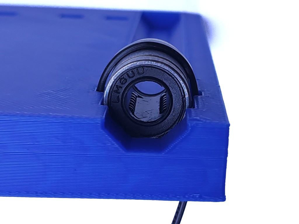
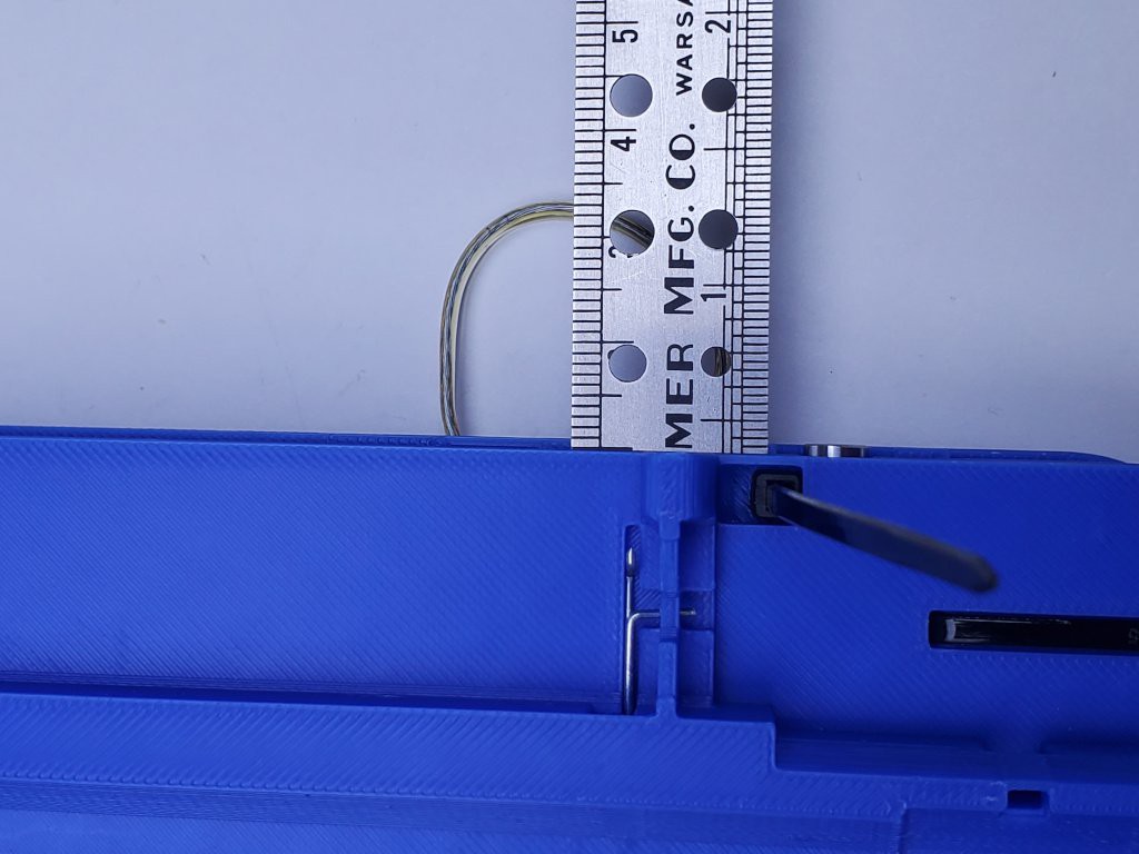
You can validate bearing clearance cleanup by dropping in a bearing and measuring the remaining clearance. That will be the hard limit to range of motion.
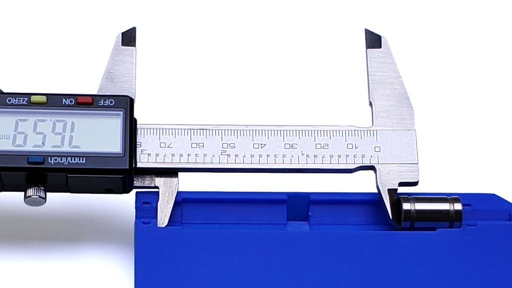
With geometrically perfect parts, that would be 77.2 mm. If I continue assembly with that part as shown, and if that's the shortest clearance of the three in that axis, I'll end up with 0.6 mm less range of motion than the CAD model. That's still comfortably more than 75 mm, which I think is ok -- 3d printed PLA after all -- and is the reason why I say ">75 mm" instead of "77.2 mm".
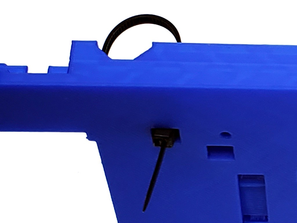
Check that a zip tie fits through all the tie passages. It may not always be obvious which way a tie is supposed to go, so the next couple of photos try to show orientations for all the ties in the "middle" part.
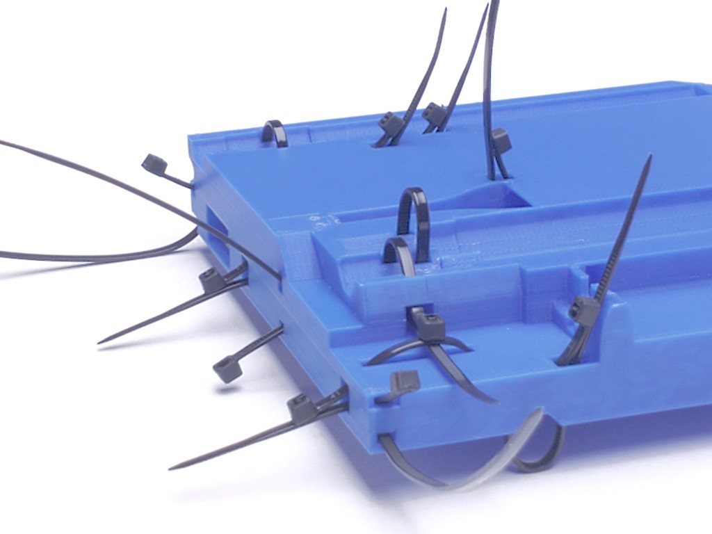
I think that part includes examples of all the ways ties are used in the "top" and "bottom" parts, so you can check those parts too.
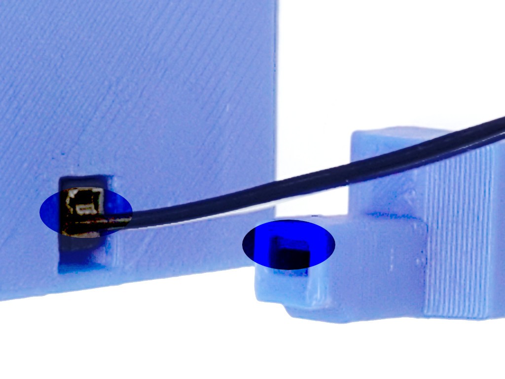
"Elephant's foot" or expanded top solid layers might constrict some of the tie head openings, so check that a tie head fits freely in any that look tight, or trim edges for a free fit if needed. It's unlikely that a head won't fit at all -- that would be really bad layer spread -- but any friction holding the head will make removal a little tedious.
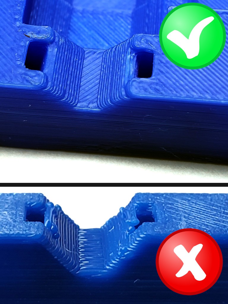
Where tie heads should not stick up, like on the top surface of the top part, make sure the bottom of the head clearance recess printed cleanly so that the head sits all the way down. Especially where the recess is printed upside down; sometimes a slightly droopy bridge that looks harmless enough will prevent a tie head from sitting below the surrounding surface.
drill for limit switch screws
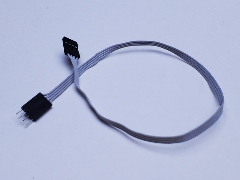
See the parts page for info about limit switches, screws, cables & connectors for the switches.
The tops of the bottom & middle parts have single layer recesses & shallow pilot holes that simply serve to show where to put the limit switches and screws. Shown in the second image below. There is a little extra solid fill under the shallow pilot holes to give the screws something to bite; that needs to be drilled through.
Using a drill somewhat smaller than the minor diameter of your screws, drill through the two marked locations for each switch. Or a warm paperclip will likely get the job done.
Or, if life has been too simple lately...
In the latest round of CAD update, I found a small error that I think contributed to the limit switches being fiddly in unexpected ways. So for this build (photo model here) I'm extra interested in the actual vs. nominal range of motion. So I wanted to try to be somewhat precise about locating the limit switch. So I did it like this:
In addition to a drill bit "somewhat smaller than the minor diameter" of my screws, I also picked one to match the nominal 1.2 mm diameter of the printed pilot holes.
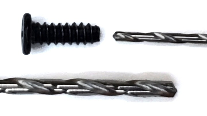
I used the ~1.2 mm bit to clean up the vaguely printed hole, and to cut a little center spot in the solid fill below. That helped with drilling the smaller through-hole in the center of the nominal locating feature.

With firm pressure for a clean start, drive a screw through each hole to form threads and make the holes easier to find blind when later installing the switches.
Re-engaging the pre-formed thread matters whenever re-installing screws in soft material. In case you didn't already know: you can do that by turning a screw slowly backward until you feel it "drop" into the thread.
Thinking: given that the screws do all the work here I can dump the rectangular depression which is vestigial.
This feels like a big nothingburger so far -- just looking & poking at printed parts. Good time to actually make ... anything? Even a little thing?
backlash adjuster lock springs
Find a couple of paperclips and make a pair of these:
Like this:
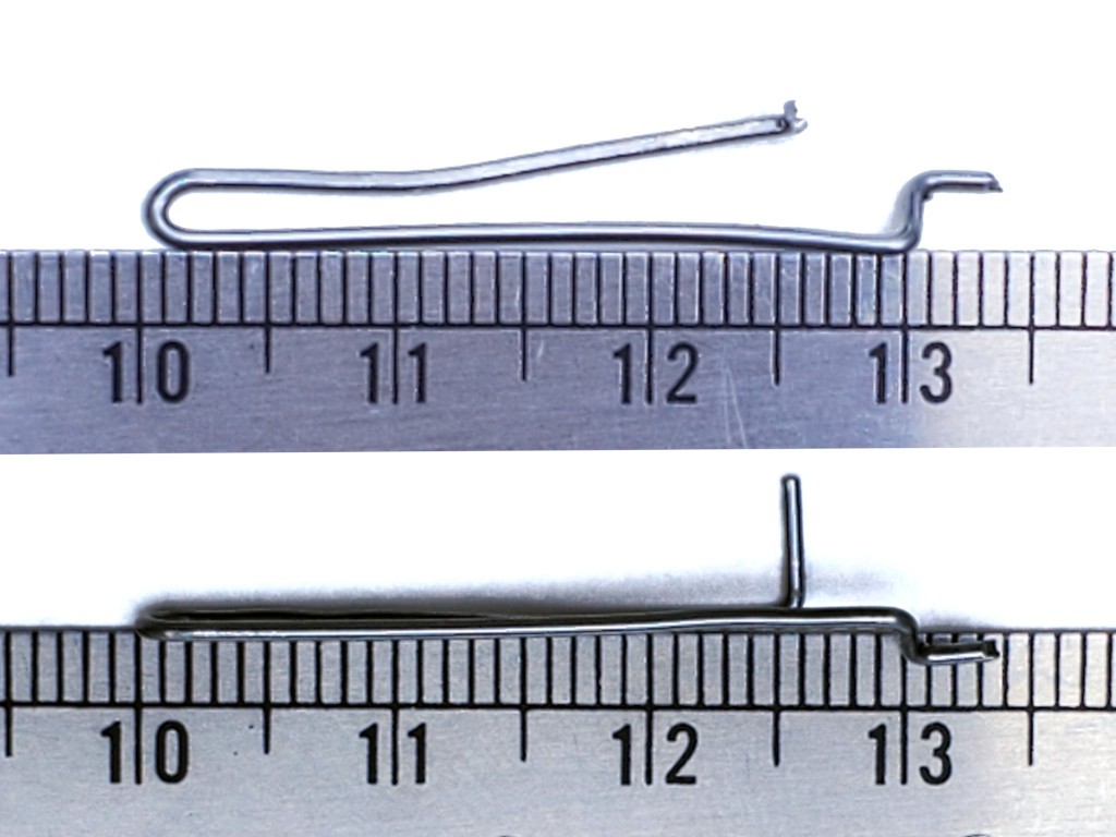
The little kick-up at the end in that pic is too tall. I think it's vestigial anyhow. Maybe reduce that to a minimal (~1 mm) turn-up at the end just enough to have a rounded end against the plastic, which will be able self-adjust position, instead of sharp end against the plastic which might ratchet the spring out of position.
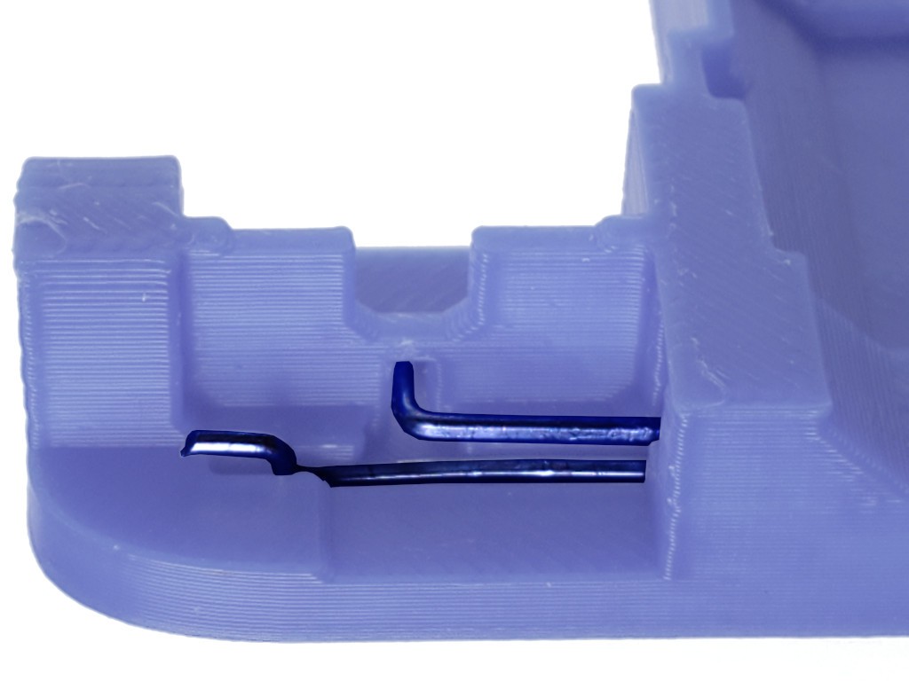
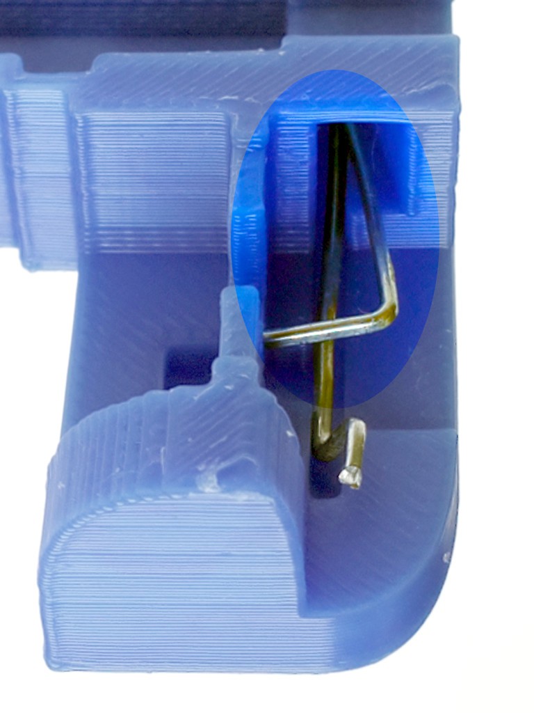
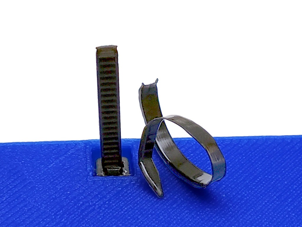
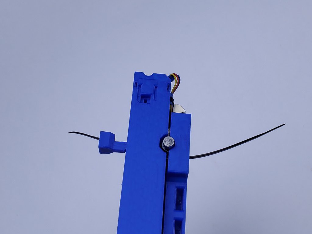
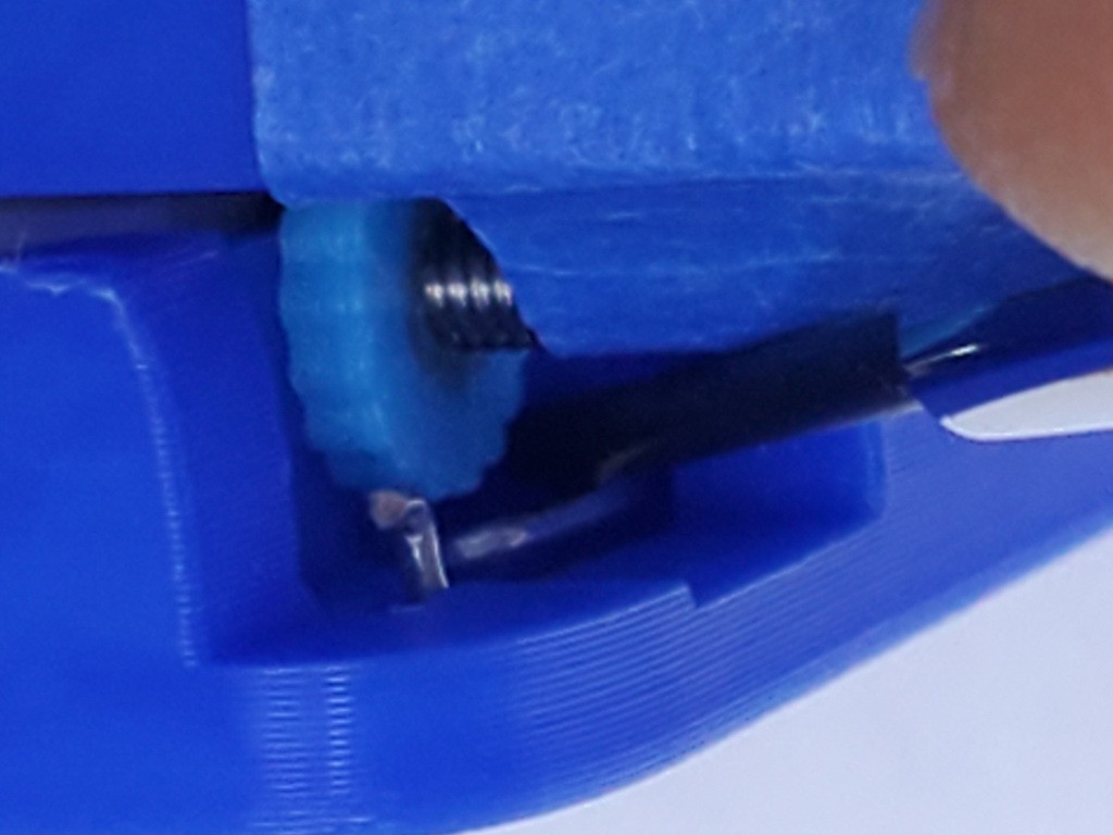
Slide the bend-ends of the springs into the slots next to the drive tabs on the bottom and middle parts. The following image shows how the relief cut allows the moving arm of the spring to come away from the drive tab until the perpendicular end falls into its slot through the drive tab.
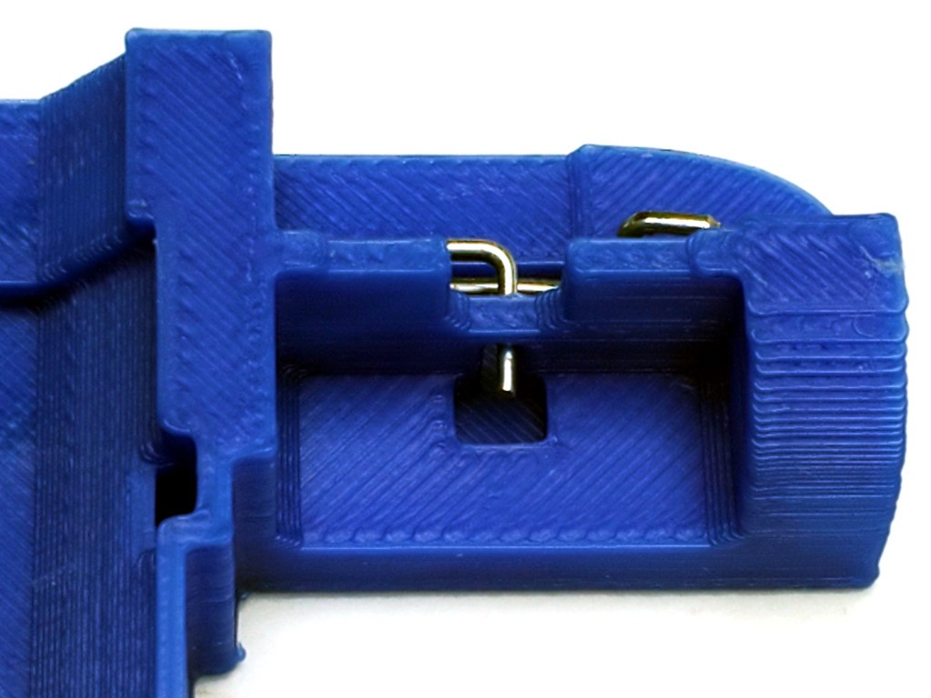
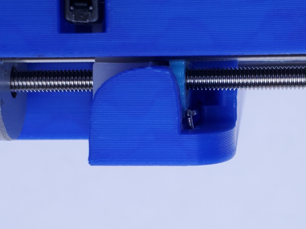
Here's another angle. The upper moving arm of the spring should allow the perpendicular end to move freely up and down in its slot.
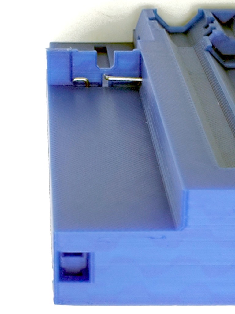
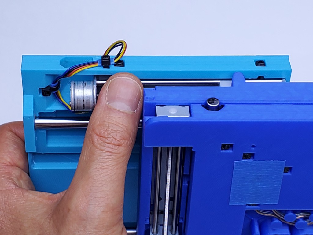
And here's a look at the other spring installed in the "middle" part:
remove backlash adjuster lock springs
Now that you have the springs sorted, take them out and set them aside for now.
Remove a spring by lifting the 90º corner up so that the spring arm lifts up out of the narrow channel into the expanded part of the opening, then back to get the perpendicular part of its slot. "Lift" and "up" while working on upside down parts as in these photos.
Repeating this photo:
![]() there are no springs
there are no springs
Believe that there are no springs in any of the following photos until they get reinstantiated in a text heading farther down.
motor prep
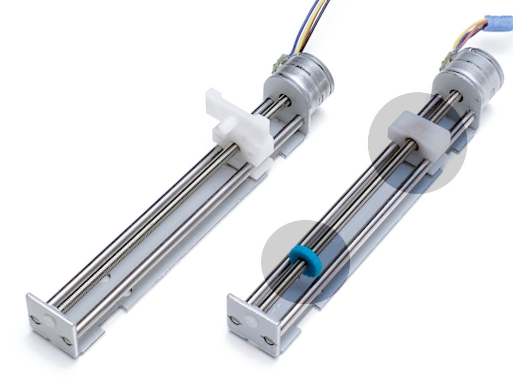
The two motor+screw units need some help to:
- trim the projecting tab from the slider (which is why the "type A" or "type B" slider difference doesn't matter)
- add a printed & tapped backlash adjuster to the leadscrew
This "Instructable" for a laser-cut version of the linear slide design used here describes how to do that. The link should drop you in at step 45 which includes the two points above:
Take care to cut only the extra tab away without taking any more material from the thin top of the slider over the internal captive nut.
Adding the backlash adjuster to the leadscrew requires [...continues...]
There are other details of that context which differ and which you can ignore because that's a different thing.
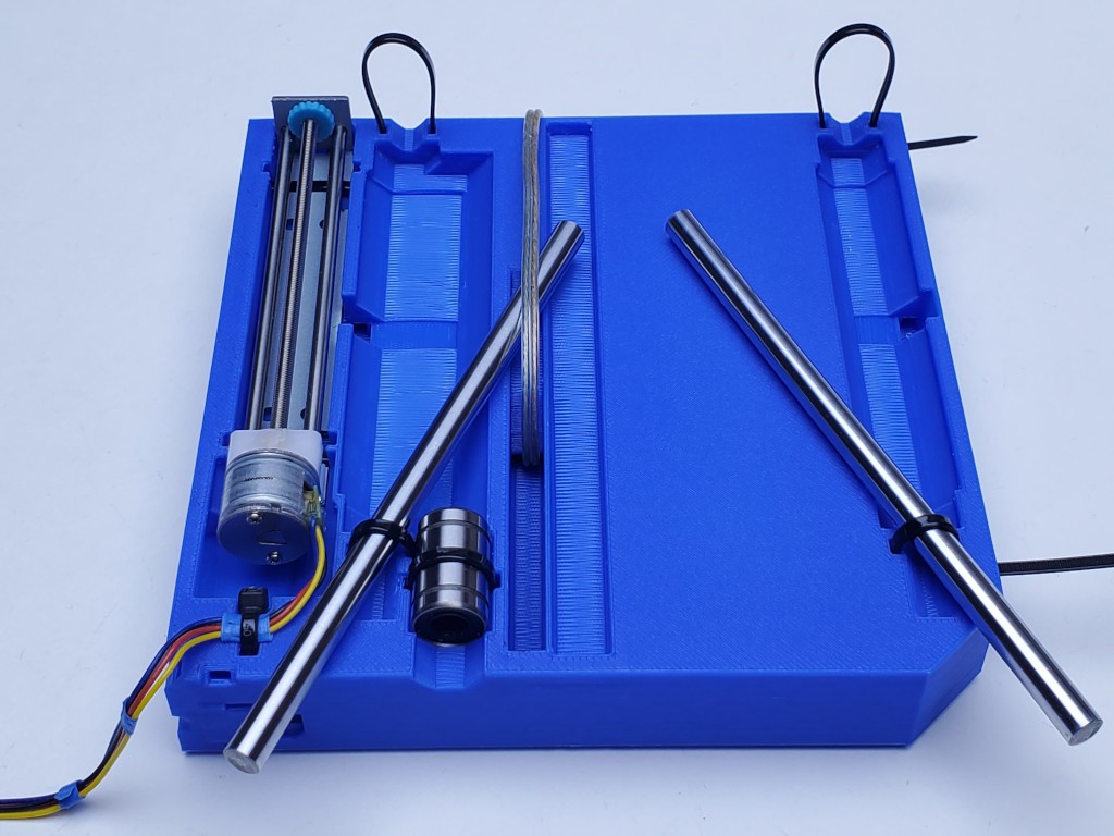
rod & bearing selection/matching
For the XY table you'll need six 120 mm rods and six bearings. If that's what you have and they're all ok, then you can skip on to the next heading.
Just ̶ ̶t̶o̶d̶a̶y̶ ̶ the day I wrote this part, a fellow HaDer reminded me that 3d printed bearings (i.e. bushings) are a thing. I think I need to look into that before I get too deep into writing this section.
In my experience of buying from low-cost suppliers, the rods and bearings I've received vary considerably in general quality and specific dimensions. It helps to have more than six of each because a few might be really bad. The rest are probably not all the same size. A little mix-and-match may help to the extent that e.g. three good rod/bearing fits may work better than one good, one great, and one poor fit.
zip tie tools
One short and one long. Probably already printed while printing parts.
And flush cutters. Please. If you have zip ties, please have flush cutters. If you're reading this you probably have a 3d printer, and if you have a 3d printer you probably have flush cutters. So, probably, everyone will be ok.
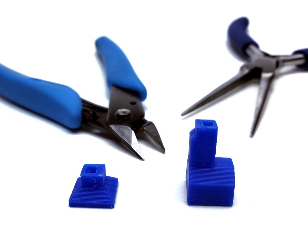
Pliers? Mmm... more about the pliers below.
With the printed tools, applied effort pushes the tie head away as much as it pulls on the tie tail to draw a tie tight.
The long tie tool can reach tie heads in deep recesses. And it's easier to use.
The short tie tool helps in a couple of spots where the tie isn't long enough to get a good hold on the tail if using the longer tool.
Secure and solid assembly depends on getting the ties tight. In part because the ratchet steps are actually fairly coarse. When wrapped around rigid stuff, getting to the ratchet step that isn't loose requires stretching the tie a bit. Then a little more stretch may get another click or three more tighter, which means more tension around parts that don't squish when squeezed. I set tie tension by pulling until the tail snaps off.
The tool has an orientation. There is a relief cut on one side of the tie at the nose that is meant to line up with the locking tab on the ratchety side of the tie.
That's there because I had a bout of trouble with the ratchet tabs failing -- even breaking off completely. That stopped when I started angling the tool (as it was then) to press on the non-tab side of the head. Hopefully this relief cut take care of that. I still try to bias pressure to the other side of the head tho, which is probably just my trauma.
For the actual pulling part, my method is pretty crude and ready to yield to better ideas.
I use needle-nose pliers with an oval shaped cross section through the closed jaws. This will be illustrated below: I grab just the tip of the tail then roll the pliers so the tie wraps around the oval section of the closed jaws which a) pulls the tail over a smooth curve instead of across a square edge where it would break too soon, and b) gives good leverage when the pliers are up against the back of a tie tool.
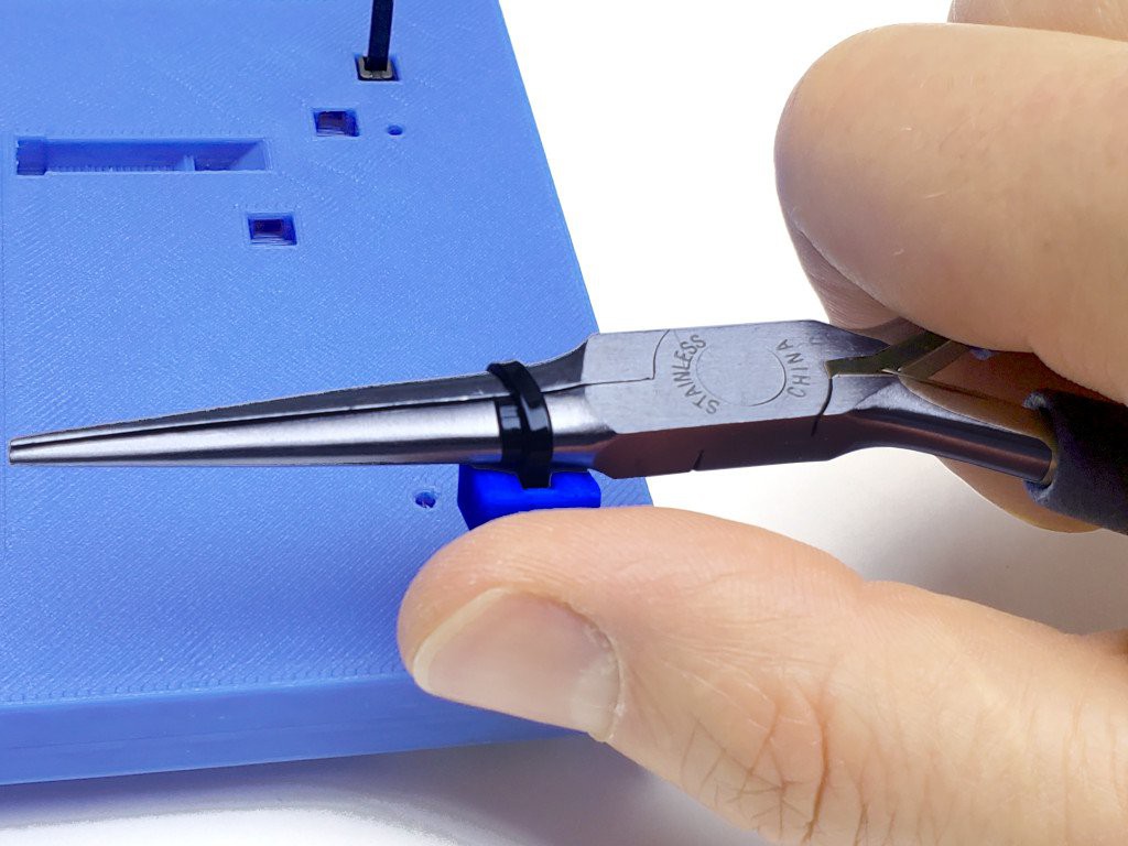
In that picture I'm pulling a tie with my right hand on the right side of the part so there is lots of room for my fingers to do stuff with the pliers. That matters in part because when the pliers are turned 90º from flat they have a lot more vertical depth. If working on a tie on the other/left edge of the part, my hand would be on top of the part. I've found that much more difficult. So I'll turn the part around so that I'm always working on the right edge. As a result I'm sometimes rolling the pliers away from myself as shown, or rolling in the opposite direction toward myself, depending on the orientation of the tie. The latter is a little harder but not awful. Maybe instead I could between right & left hands instead of switching roll direction in the same hand.
Anyhow... while maintaining a straight, even pull, keep cranking until the tie tail breaks.
And cut the remainder off flush. Or below flush for more deeply recessed ties.
That process may be no fun to pick up cold. It's the process I've developed over some time without any intentional deliberation. So it may reflect some awful local maximum that no one else would have blundered into in the first place.
A bona fide tie tensioning tool might work great in combination with these printed tools. I don't have one. None of the tensioners I.ve seen (picture of) have a narrow nose to press the tie head below surrounding surfaces, but any one of them might work well behind one of these printed tools.
After writing all this section, which makes me think about stuff, I've ordered a $12 tensioning tool that should be here tomorrow.
assembly order
Y/bottom then X/top.
(In theory it's possible to split and re-assemble Y after building X. There's an extra hole in the top to make that at least not impossible. It might require making another zip tie tool for a tie that will be at best awkward to reach. If this turns out to be not actually practically doable, then I should delete the extra hole in the top.)
install bearings
Yay - finally time to assemble something! [ ̶i̶n̶s̶e̶r̶t̶ imagine confetti gif here]
I install bearings first because they are least fragile, have no wires, you can install them all at once in any order or six at a time as you assemble each of the axes, and once in place they just become a part of the solid part.
In the pix below I build the Y axis completely before installing X bearings. You could also do all the bearings at once.
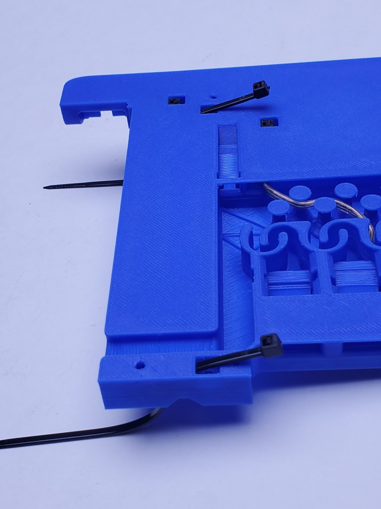
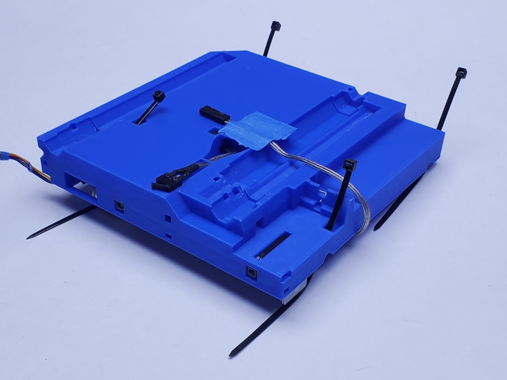
Anyhow... start by stabbing a couple of ties through the bottom part in the places and orientation shown below:
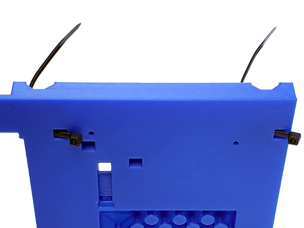
Turn each tie back down through the bottom part and through the tie head. Leave loose loops above. Like this:
Drop a bearing into the bearing-length V-block under each tie loop. Pull the ties firmly hand tight to hold the bearings.
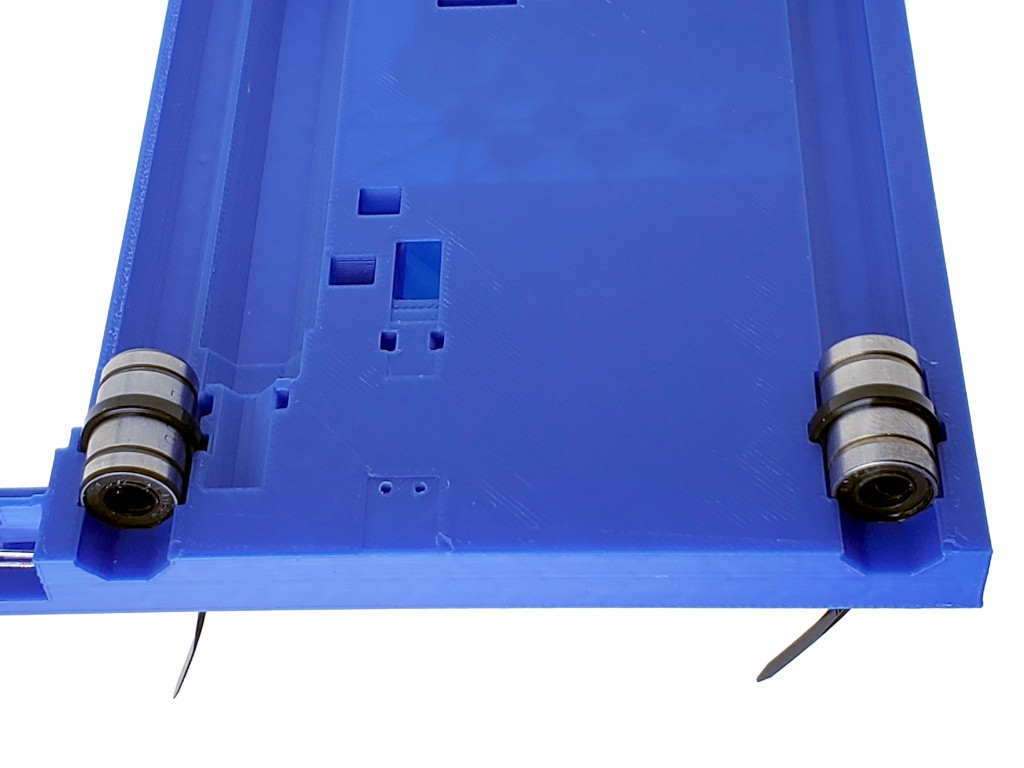
As a minor optimization, I like to rotate the bearings to move the four ball races to the 45º positions because I have an unsupported conjecture that peak loads will be either vertical-ish or horizontal-ish more often than on diagonals.
Crank the ties down hard as described in the zip tie tools section just above.
The tie heads should be recessed to flush with or below the bottom flat surface.
The third Y axis bearing attaches to the bottom of the middle part. Insert the tie for it through the top of the middle part.
Add that bearing and pull the tie hand tight. This time you'll notice, if your ties are like my ties, that the long tie tool leaves only the thin end of the tail to grab. This is where the short tool helps.
If you like your momentum, you can install the X axis bearings too,
install Y/bottom limit switch
See the parts page for info about limit switches, screws, cables & connectors for the switches.
For the bottom part, use the switch prepared with the shorter wire.
(If you don't want to mess with specific wire lengths and/or DuPont-type connectors in the base, you can just use generously long wires lead out into free air. If you plan to use connectors that won't fit through a 0.1" x 0.2" hole, (or a 0.4" hole if you will have motor wires outside also) leave those off until later.)
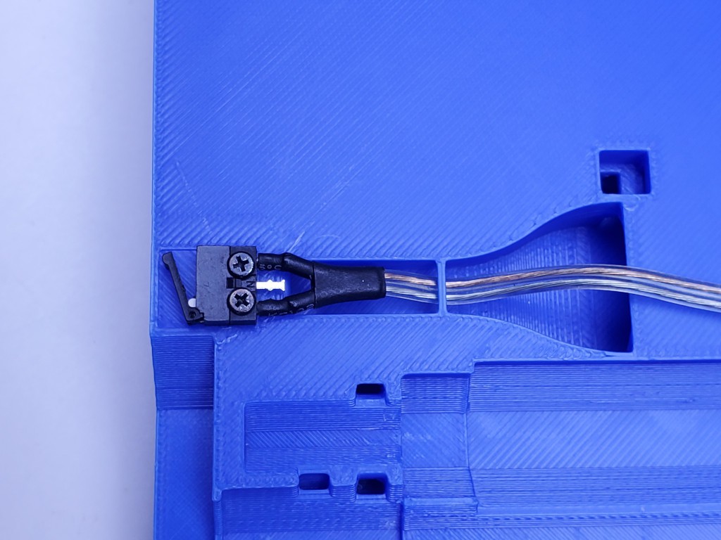
Pass the wire tail through the bottom part and screw the switch in place. The orientation of the switch lever doesn't matter.
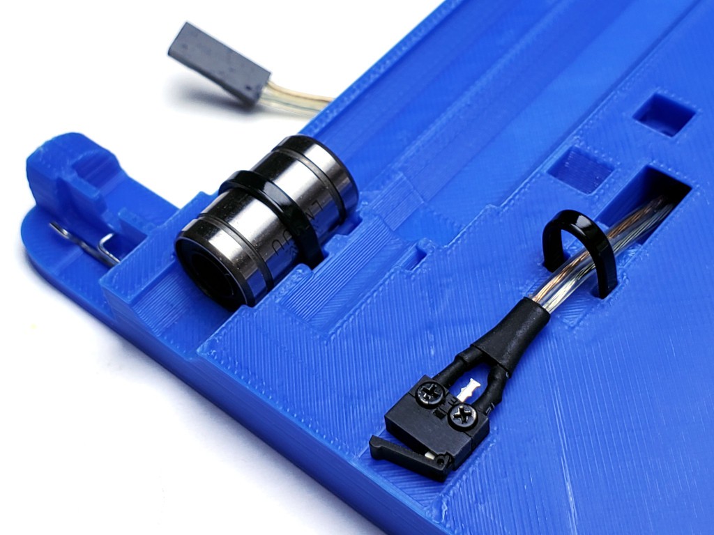
Use a tie from below to secure the wire for strain relief. Pull that tie tight enough to prevent the wire from slipping when moderately tugged, but also note it's pretty easy to overcook that.
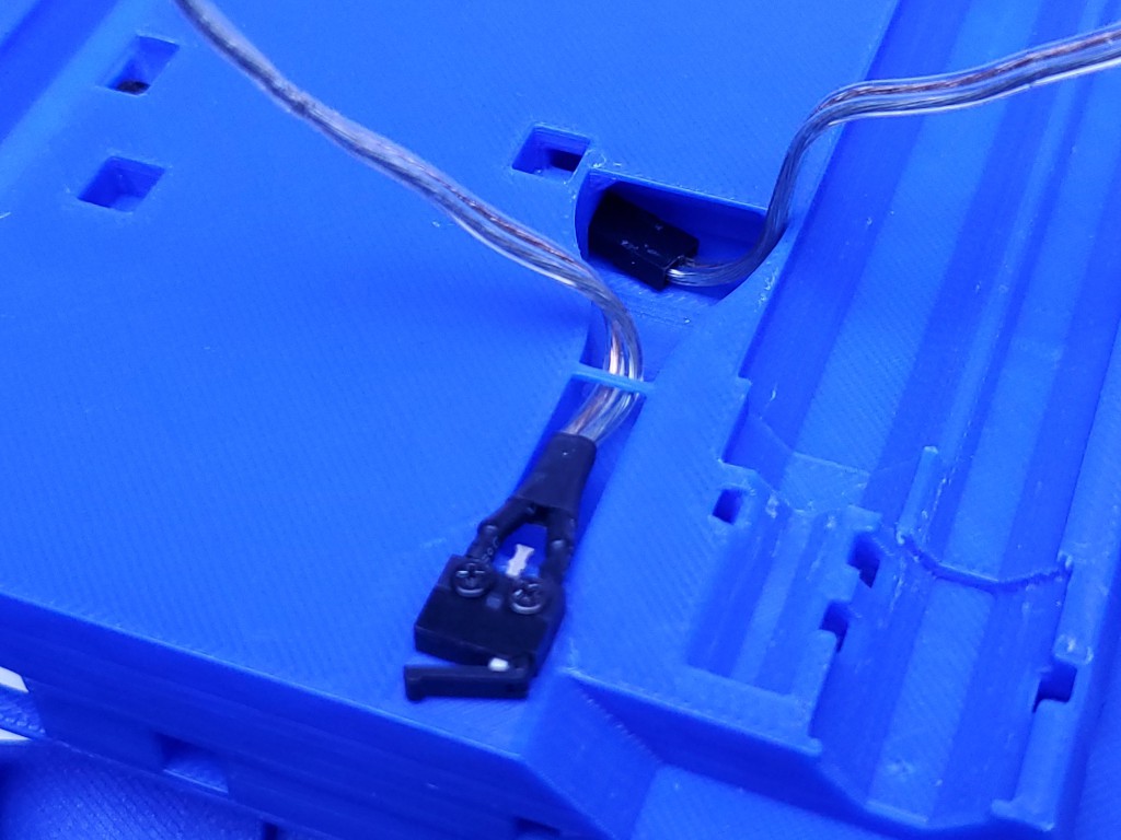
Secure the connector in place with another tie and arrange the wire.
The connector housing should back up against the slight ridge behind it. The tie has to be fairly tight to prevent the connector from riding up over that ridge when pressed inward. (Maybe I can make the ridge a little higher -- but not by much. but maybe enough to make this less easy to miss)
Pull the wire back just enough to take up slack from the connector, then lay it into the serpentine strain relief, That is to hold the connector in place when pulling out a connected cable, but more kindly so than with a cable tie because this is actually intended to get pulled on. Lay excess wire around the pegs as needed to use up slack in the middle,
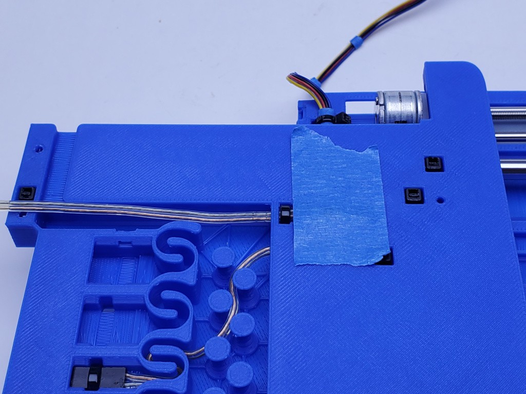
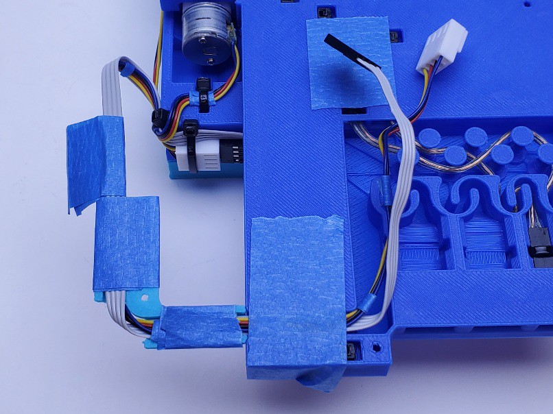
install X limit switch
(ok, ima lay off the picture tweaking for now... (later: up to 91 pix now - am I going to clean up 91 pix for this? :-/))
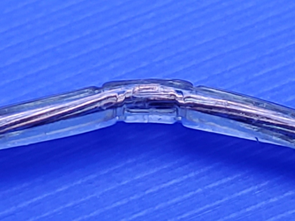
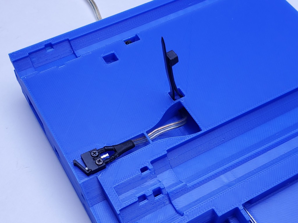
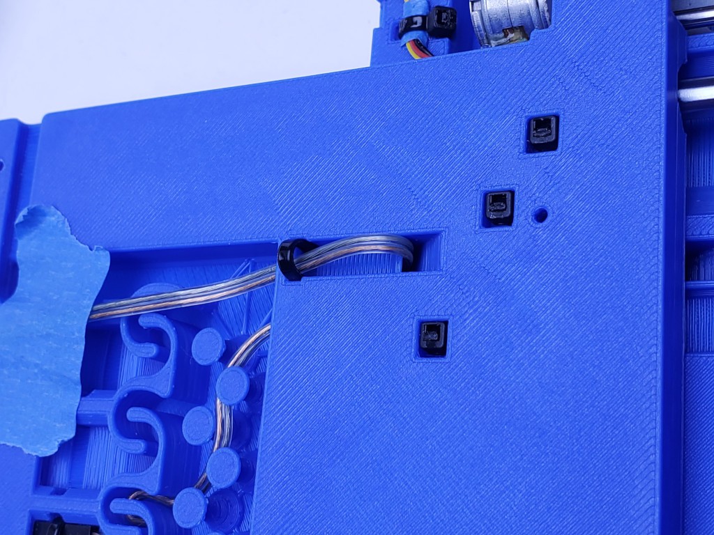
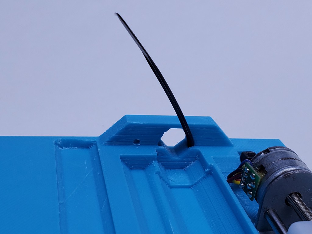
Pass the X limit switch cable underneath the little bar across the opening behind the switch, then attach the switch in its place.
Pass the connector housing sideways under the ledge behind the switch, all the way down and back, and slide it into the opening to the left.
Continue to feed in the switch cable until you can grab it from the underside of the part. Then, taking care to keep it from twisting, continue to feed all the cable through until just a relaxed bend around the top-side corner remains.
I usually have to simultaneously pull and feed to get the cable to slide through without jamming.
The design idea behind not letting the cable twist is that the moving part should make a rolling bend like a flat flex cable. I don't know how important that is really. I find it easier to start flat and keep it from twisting than to untwist it, because where it passes through the middle piece that part of the cable is out of sight and hard to manipulate. All assuming flat side-by-side cable construction.
At this point I find it helpful to wrap the cable back up around to the top side again and tape it in place keep it flat
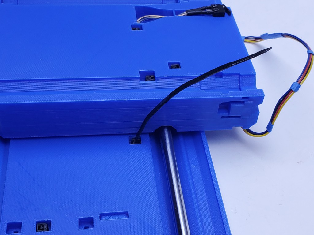
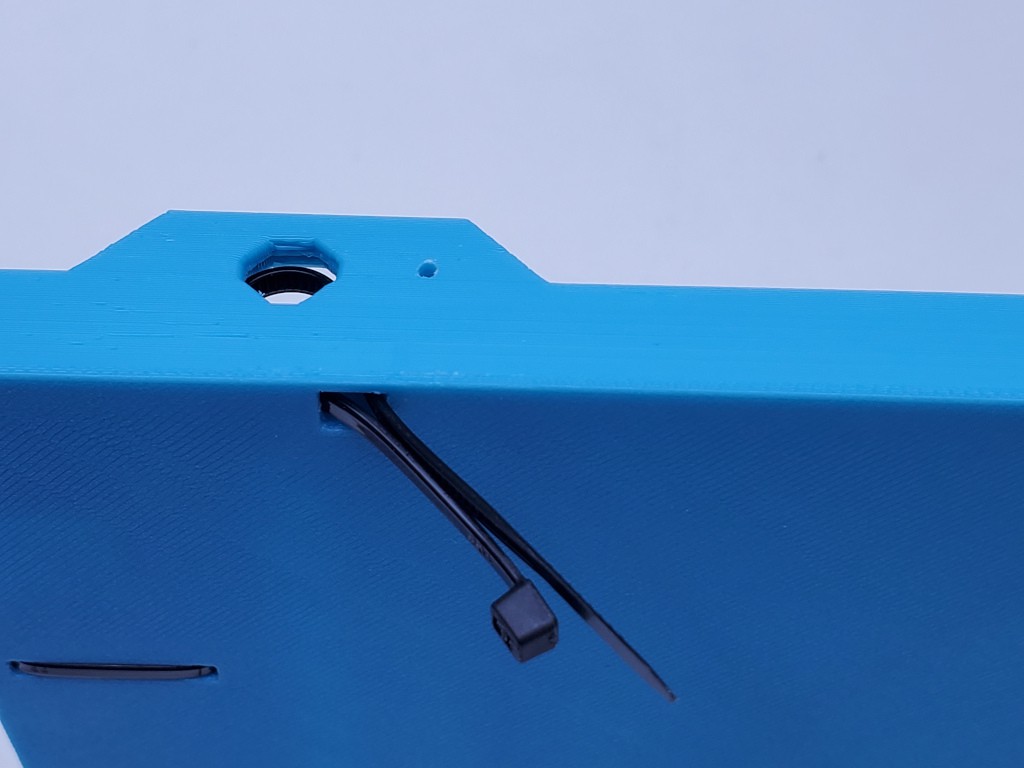
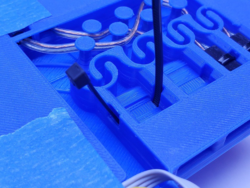
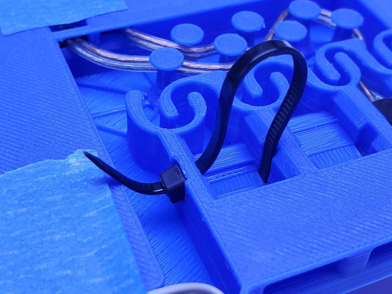
To secure the top end of the moving part of the cable, insert a tie through the space next to the top side opening. The tie should be directed around a tight bend and come straight back up.
Give the two ends a pull together to make sure the tie went around under the switch cable. The zip the tie into place and tighten it just enough to keep the cable from slipping when pulled moderately.
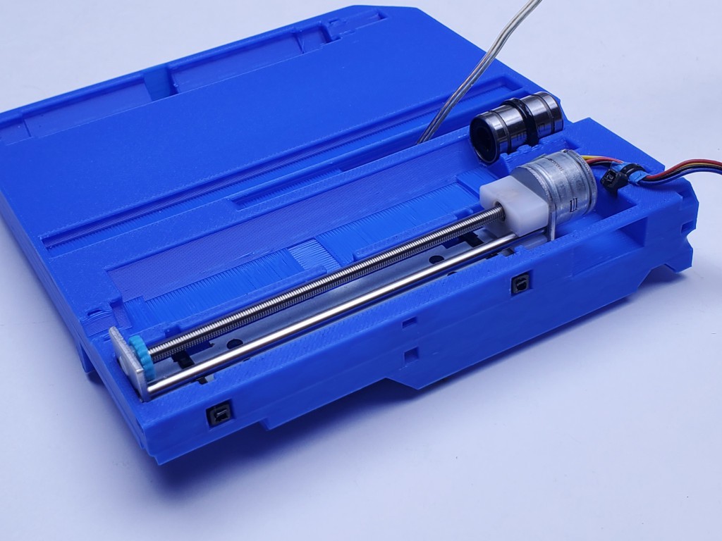
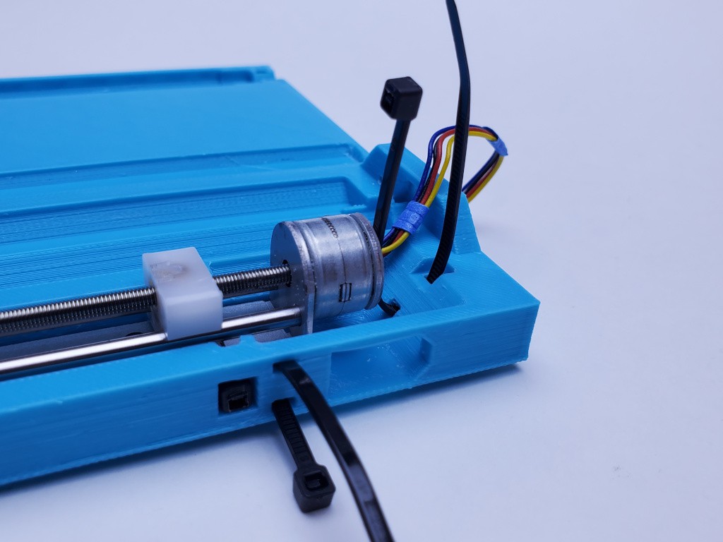
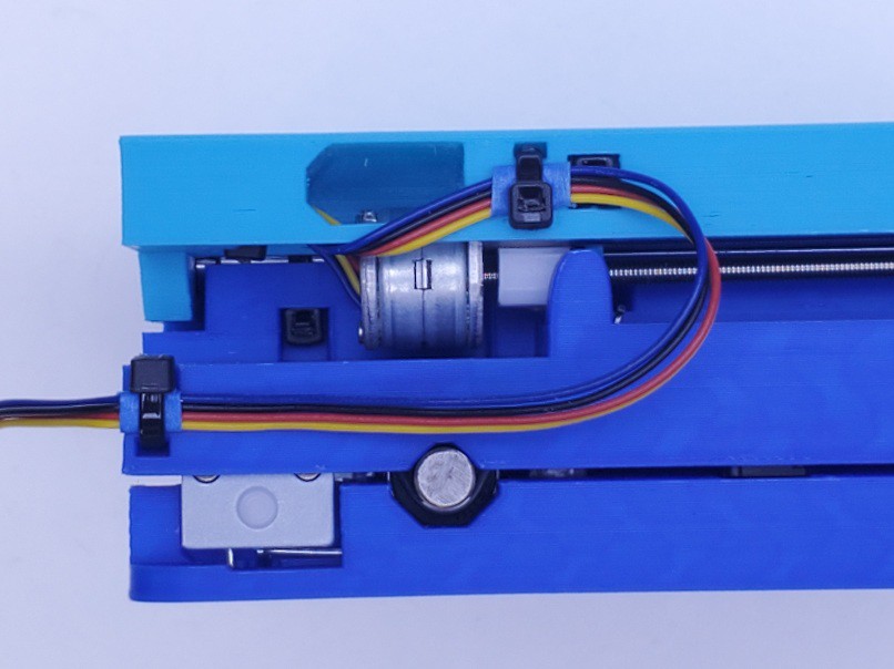
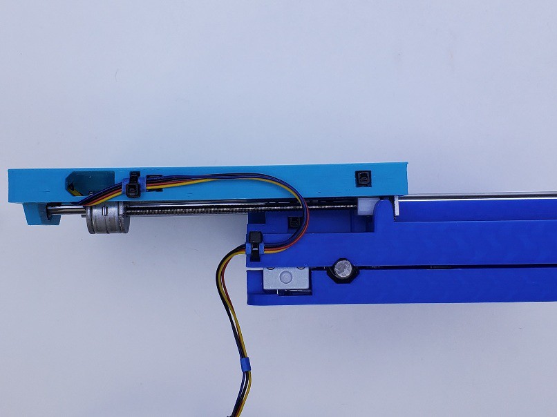
install Y motor
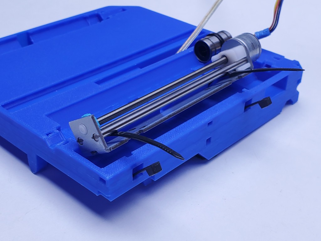
The Y motor fits in the big rectangle on the bottom side of the middle part. It should have clearance along the sides but fit tightly end-to-end. It will likely deform the small wall at the motor end a little but take care to avoid breaking that.
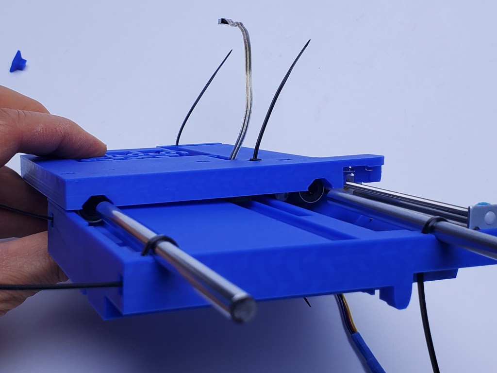
Spin the leadscrew and backlash adjuster to move the motor's slider to the motor end of the screw and move the backlash adjuster to the opposite end, as in the pics below.
Insert two ties for the motor through the middle part and also through the motor frame underneath the two fixed rods before completing the loop back to the tie heads.
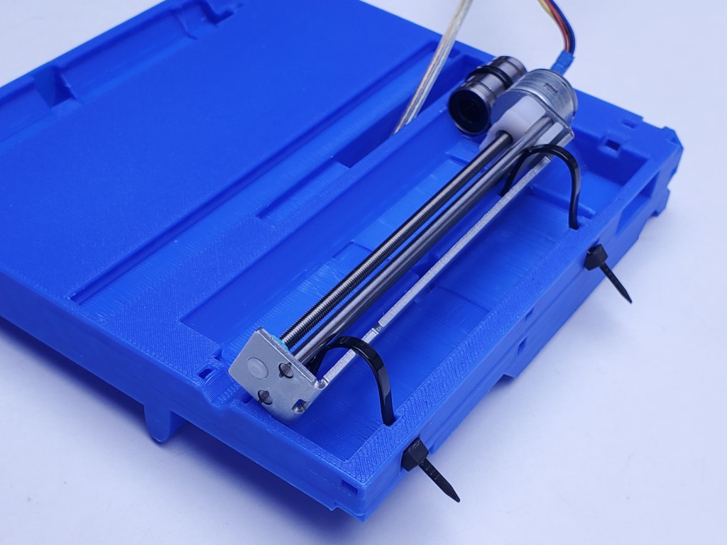
(clearly I hadn't taped the switch wire back yet -- apparently it was behaving well)
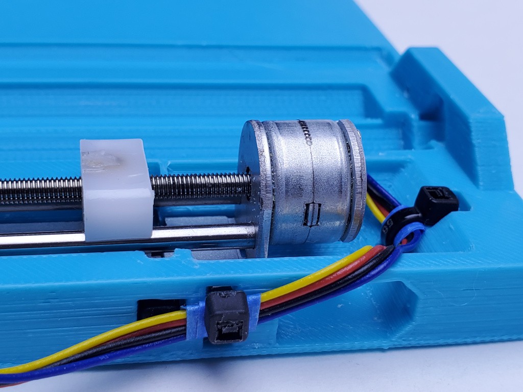
Rotate the motor into place while drawing up the ties hand tight. Then check that the motor fits flat and tight into place at both ends while tightening the ties up hard. Also add the tie behind the motor to capture the motor wiring for strain relief.
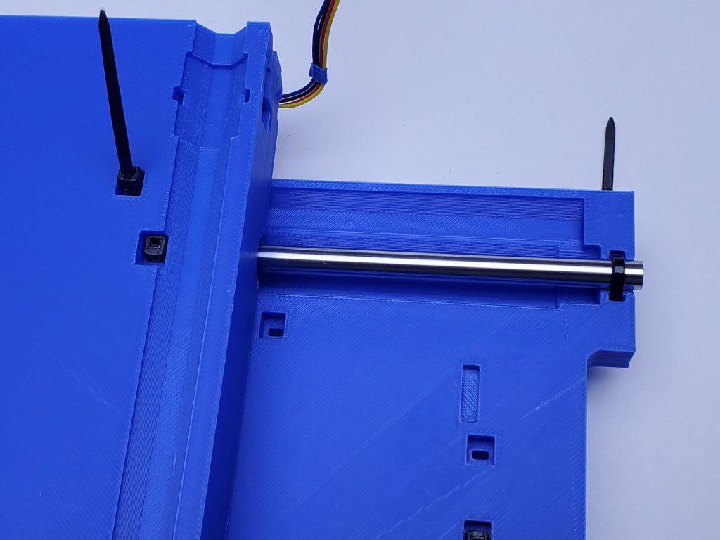
pre-set Y lower rod
Insert two zip ties through the bottom part.
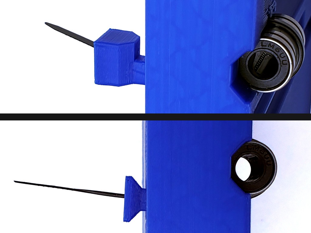
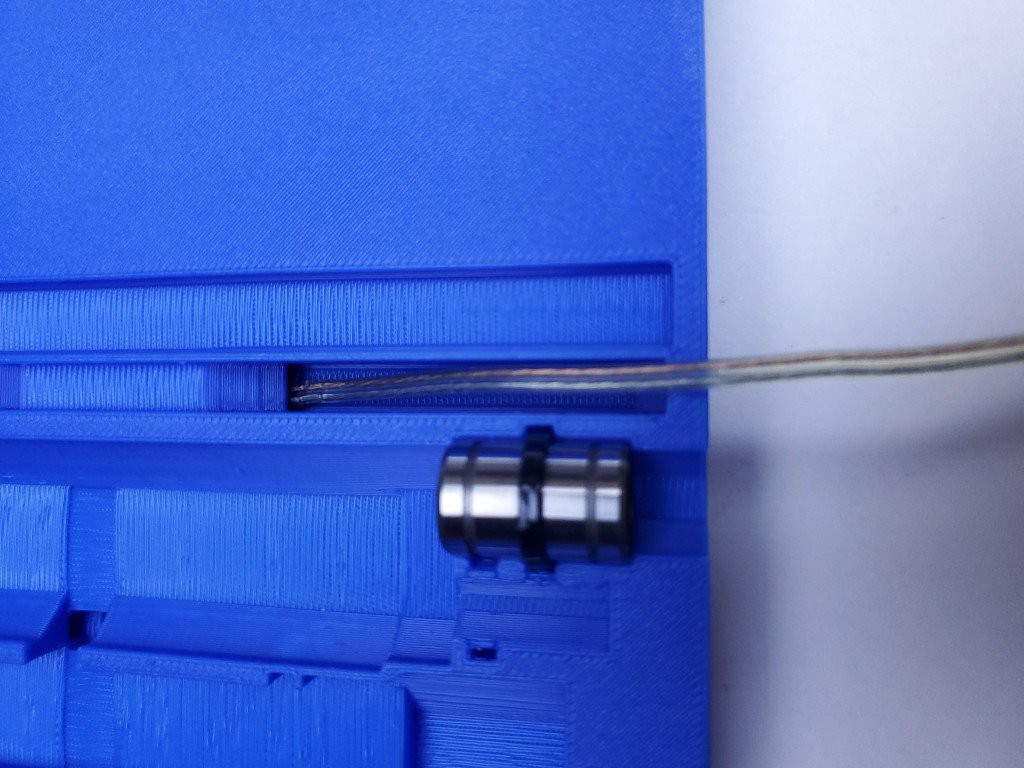
At the end between the switch and bearing, draw the tie down to a loop that is not too small nor too big but just right. An easy way to do that is to lay a rod diagonally across the top surface of the part and draw the tie down over that.
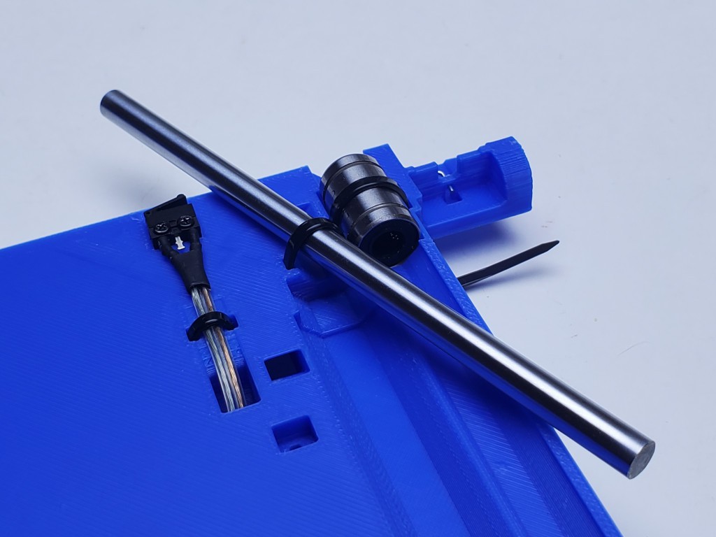
Close the tie around the other end, and pull that one firmly hand tight. You want it tight enough so that you can handle that part without dropping the rod out. Leave both tie tales.
(The part uploaded here actually looks more like:
)
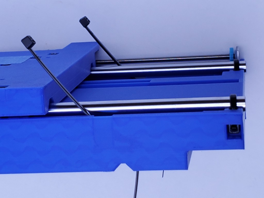
pre-set Y upper rods
Insert four zip ties through the middle part.
(...now I have the X limit switch cable taped up)
Set the not-so-tight ties at the motor end by pulling them down over a rod laid diagonally across the surface of the part.
Pull the ties at the other end firmly hand tight, enough so that the rods don't fall out. The heads of ties on the left are slightly recessed, so you may need to use a tie tool to pull that one tight enough.
That's all the parts for the Y axis. This is a good place for a break if you need before getting into the next sequence.
heads up
You have no springs installed. You believe there are no springs in the following photos. RIght?
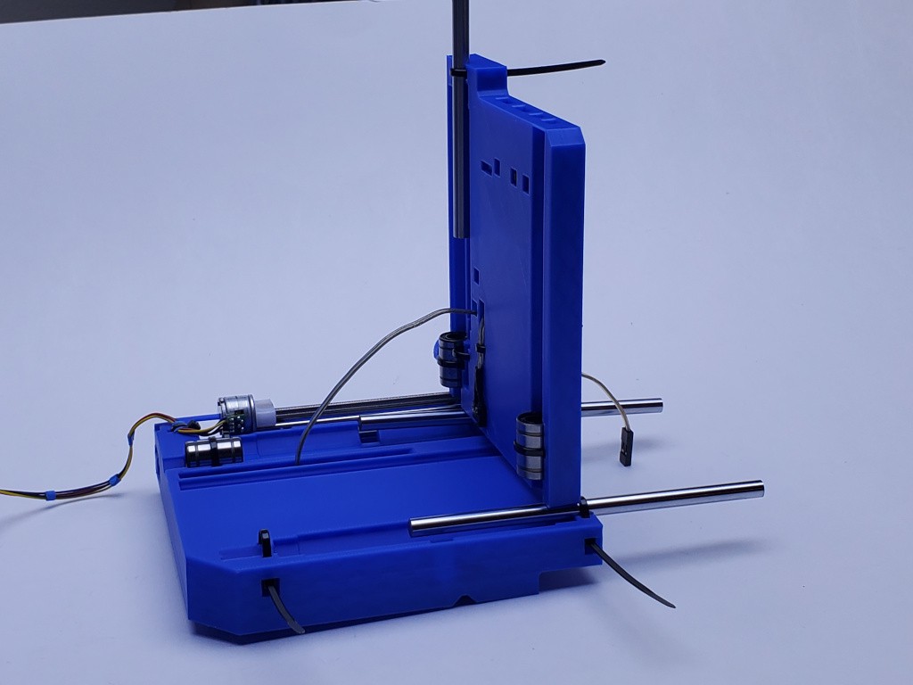
Y axis assembly
On the lead screw, check that the slider is against the motor (just in contact, not jammed) and the backlash adjuster wheel is at the opposite end against the bushing (just in contact, not jacking the screw of its bearing).
Pull the three rods half-way out.
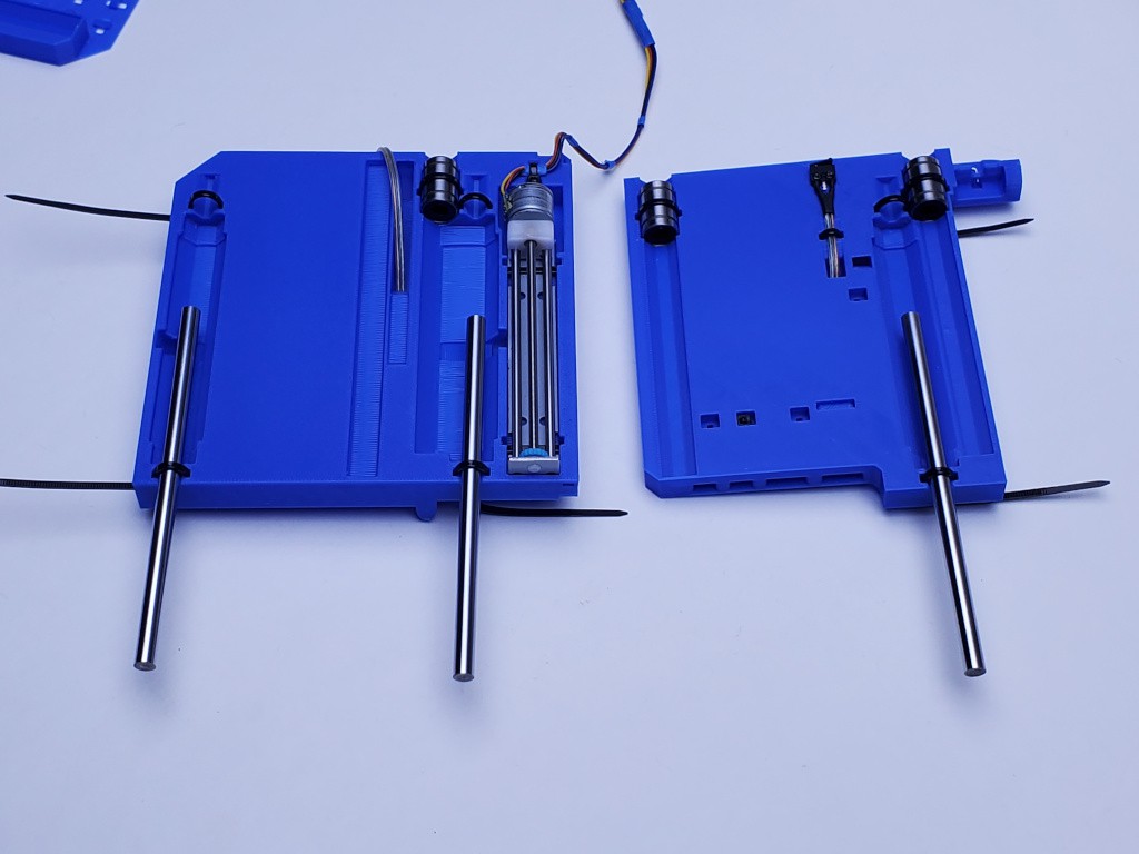
Lay the two parts side by side as shown below. Bring the X switch cable across and start the connector through the angled hole in the bottom part
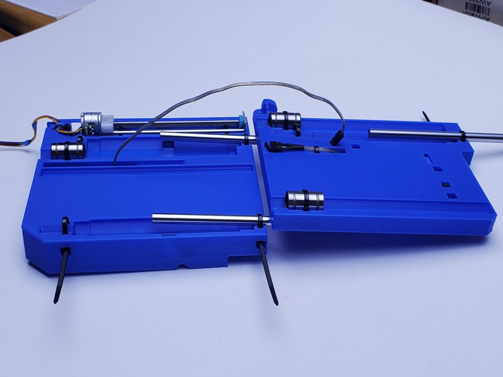
This is easier to do than to describe: While folding the bottom over the middle like a book page, feed the switch cable through the bottom part -- which really means the switch cable doesn't move much while the bottom moves around it.
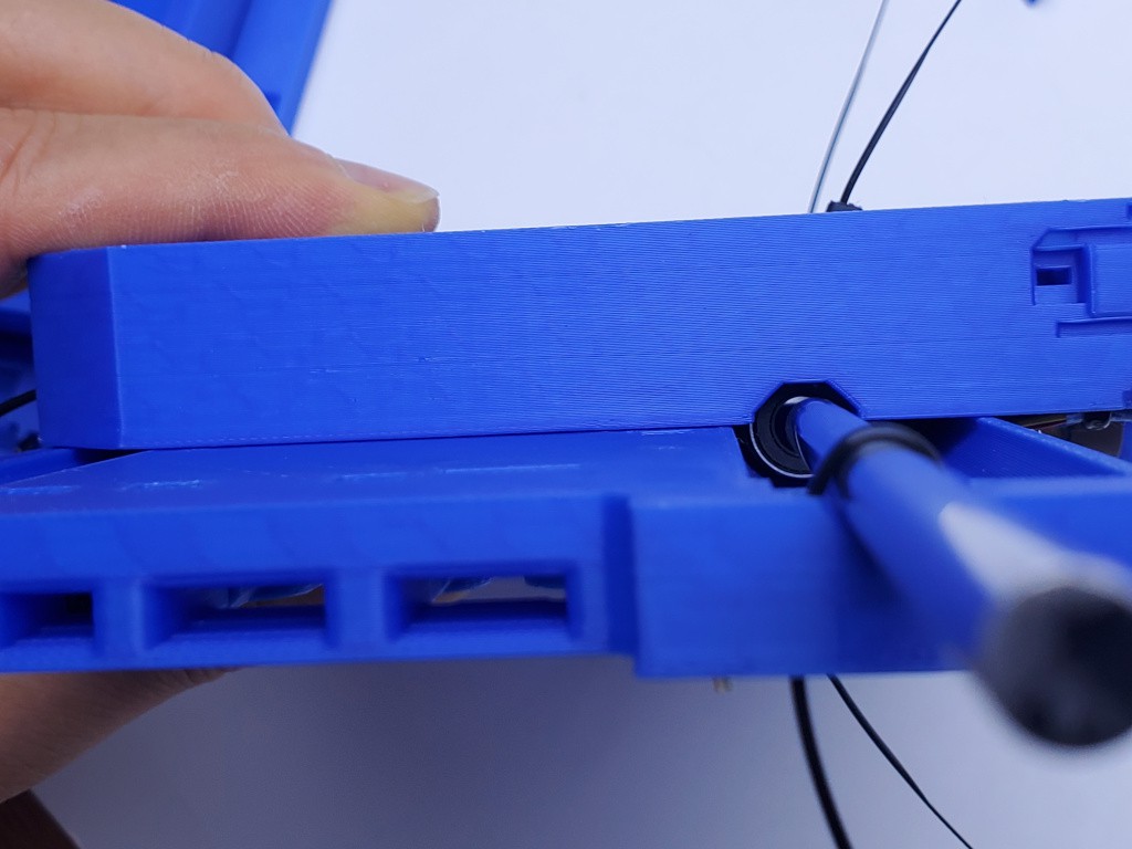
When the bottom part is "folded" over onto the middle, slide the bottom (which is on top) to the left. It should meet a hard stop where the bearings hit the end of their clearances.
Line up the end of a rod with its corresponding bearing and, carefully, work it through the bearing.
Beware: the rod and bearing aren't really aligned at this point and the end of the rod can do bad things like strip out bearing balls. Go slowly and carefully until the rod end clears through the bearing. Nice chamfer helps but I don't know how much is safe enough to not care.
After the rod is through the bearing, work the end into its V-block and under the now-buried tie that is not tight. You may have to lift a little, and not squeeze the two parts tight together, to get the end into the V. Then hold it down to get it under the tie. Make sure the rod end goes all the way to the hard stop. Leave the loose tie loose for now to allow a little float for fitting the remaining rods.
The rod in the photo is a little long: it is all the way in while also overhanging the visible end a bit.
Again with the remaining rods: carefully through the bearings...
... then fully into the V-blocks, under the loose ties, and all the way to the hard end of their clearance.
With the slide fully extended as shown, pull any slack out of the switch cable then let it relax and give back just a little slack. Hold the cable with a fingertip or some tape right where it comes through the bottom part.
Now you should be able to run the slide freely from end to end. It should stop sharply at both ends with hard contact. There should be visible separation between the drive tab and the lead screw slider at the hard limit of extension, and between the tab and backlash adjuster when hard closed.
Close up the slide to its hard limit, then push it hard against that limit to force the bearings to the limit of tolerance in their positions. You may feel one or more of them shift.
When the bearings are set against the surfaces that you checked and dressed way back at the beginning, the slide should overshoot "zero" closed alignment by about 1 mm.
From this point you want to avoid hard contact at the opposite limit, which will knock the bearings out of place. If you do hit the opposite stop, just repeat pressing hard against the closed stop. Hard contact at the limits will be easier to avoid after the slide gets coupled to the lead screw.
Check if you can hear the snap action in the limit switch. If not, use a meter to monitor continuity and verify that the switch works (which would be prudent even if you can hear it but that's not the point at this point).
Carefully find where the switch just snaps over open or closed. If the overshoot shown above is close to 1 mm, then the switch should toggle (mechanically close, electrically open) when the overshoot is about 2/3 mm, or just before hard contact. Carefully reversing back from that position, the switch should revert when the overlap is about 1/3 mm, or when about 1/3 mm back from where it toggled.
The main thing is that the switch must toggle before contact with the hard limit. Secondary to that, it is meant to toggle between "just" and about 0.5 mm before hard contact because I like a short limit pull-off distance because the axes are short. If it toggles closer to 1 mm before hard contact, that's uncomfortably close to the switch body being the hard stop. So the main main thing was that the switch body wasn't ever the hard stop in the first place because if it was then it wasn't anymore after pressing to set the bearings.
For easier handling, secure the slide closed with a piece of tape across the two parts on the side parallel with the axis. Also wrapping the limit switch wire around to the top side and taping it there will help keep it flat from twisting.
Check that all three rods are pressed all the way to the hard end of their clearance, and fully tighten the six zip ties.
Use the short tool for this tie because the long tool leaves only the thin end to grab.
Yay. That was a bunch of tie-winding.
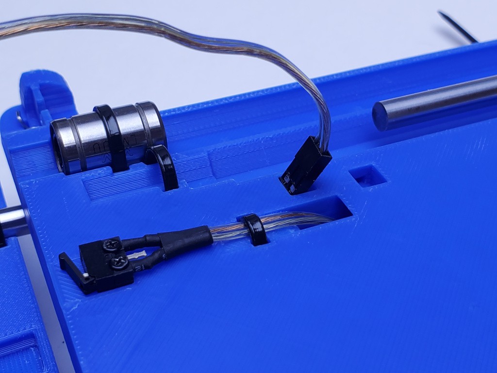
dress the X limit switch cable
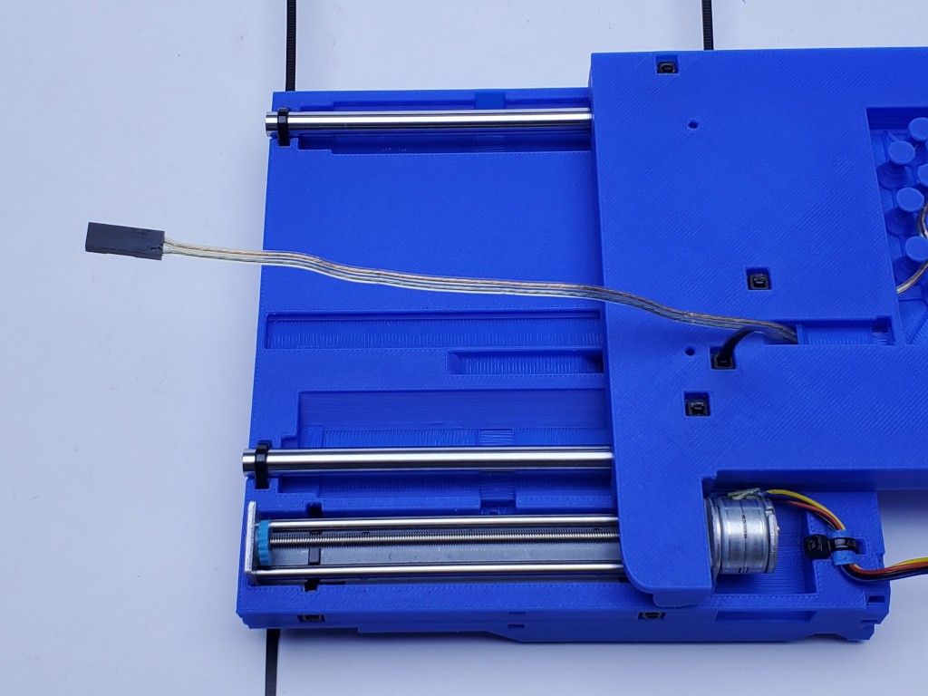
Flip the Y assembly over. Pass the switch cable under the bar at the end of the opening as shown:
For convenience you may want some tape to hold the cable.
Note the slide will probably not run freely because it will probably push the cable up here approaching mid-travel, where it will jam instead of pulling back down. That's ok. It won't happen when the stack is attached to something else.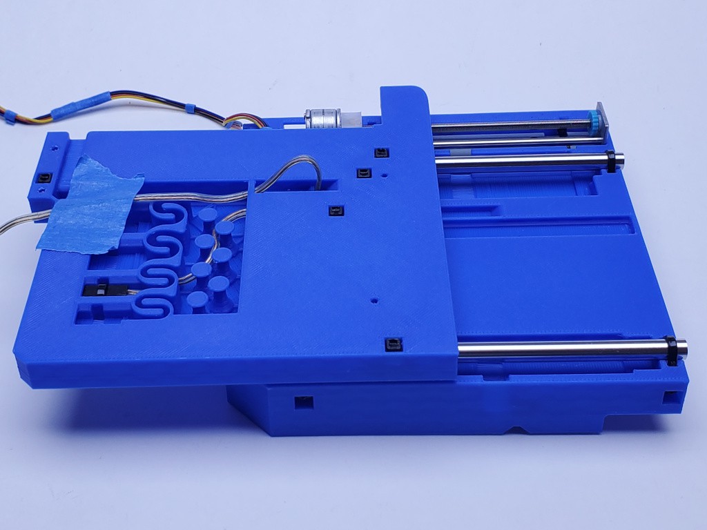
Fully extend the slide. You may have to hold the cable or help it feed back down while moving through mid-travel.
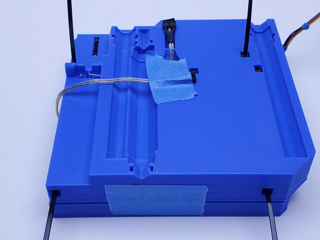
Insert a zip tie through the position exposed by fully extending the slide, turn it back up and through again, capturing the switch cable.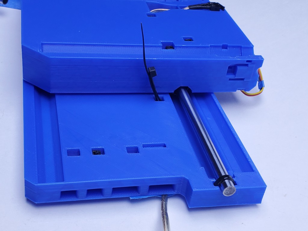
While holding the slide at full extension, re-adjust the position of the cable as before: pull out slack, then let it relax and take back a little slack. Tape over the opening to hold the cable in the position it will take when the unit is attached to another surface. Verify that the slide will rest against the end limit with no spring-back from the cable. Adjust if needed. Pull the tie tight enough to keep the cable from sliding without cutting the insulation.
Cut the tail off flush to let the slide move.
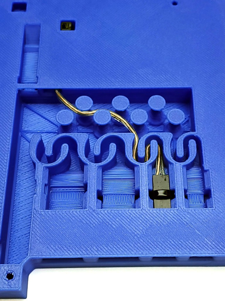
Repeating the process as with the Y switch cable, zip tie the connector housing in place against the ridge behind it, pull slack out of the cable and lay it into the serpentine path, and lead the rest of the cable around the pegs as needed to use up slack.
A nicer piece of tape over the cable opening will keep the slide easy to handle as a unit by itself and, in my experience, isn't too thick to leave in place when mounting the axes for use.
When it's all buttoned up and right-side-up, make sure the slide runs end-to-end and there is no spring-back at either end.
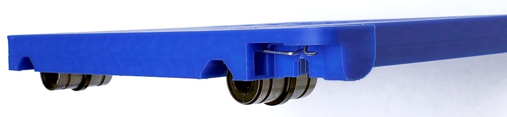
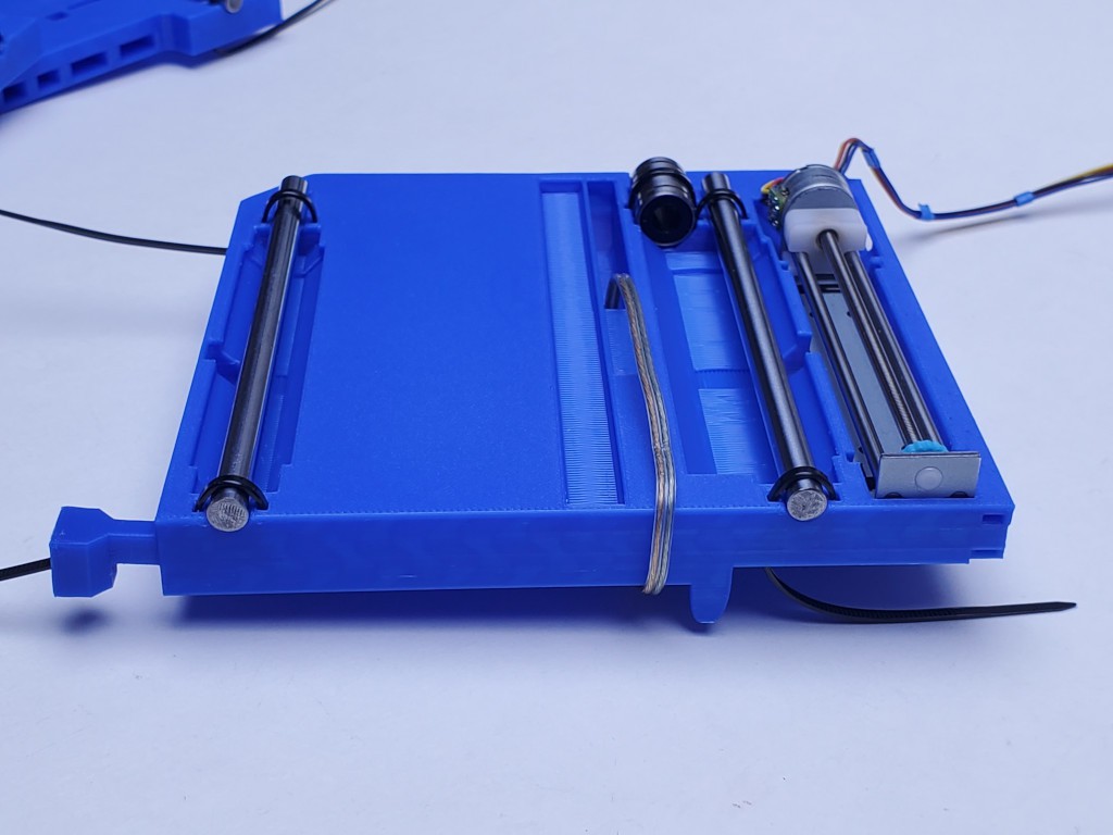
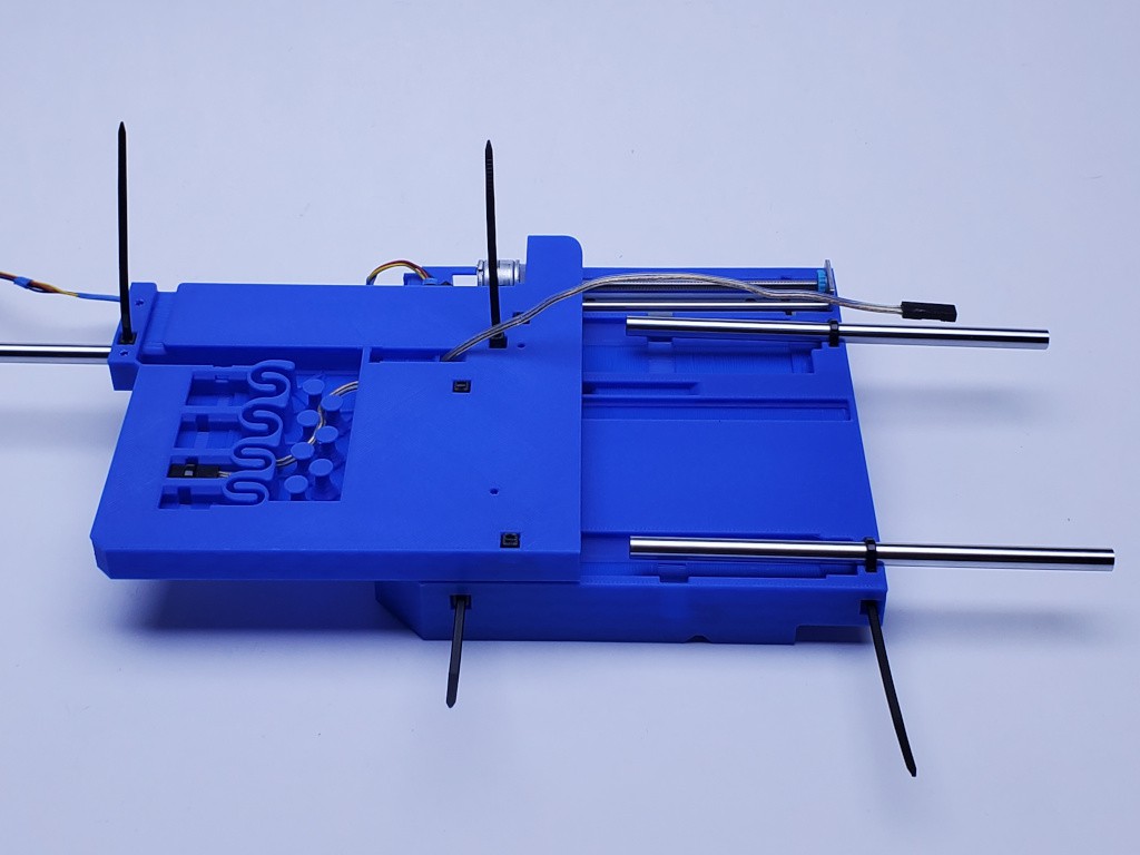
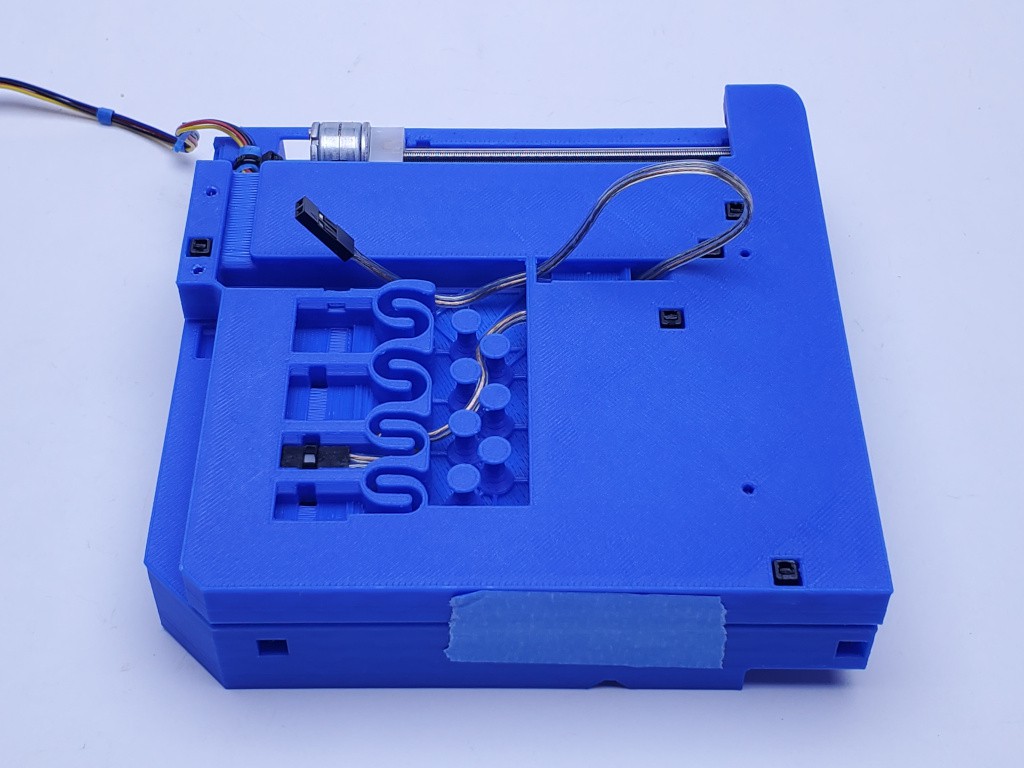
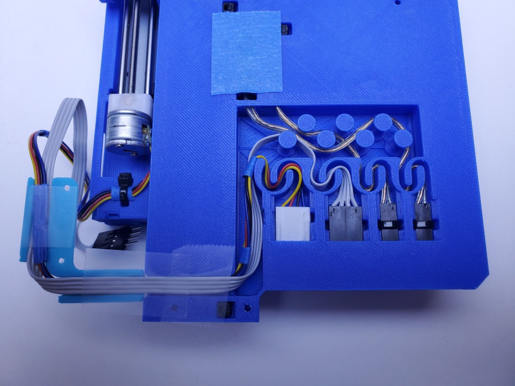
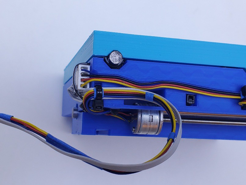
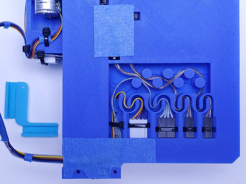
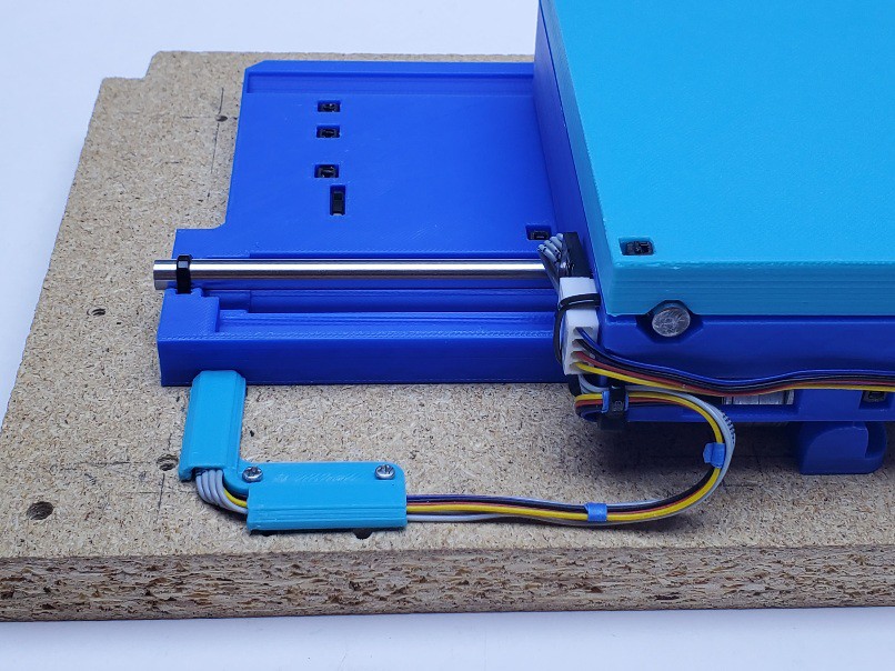
preview
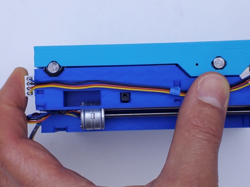
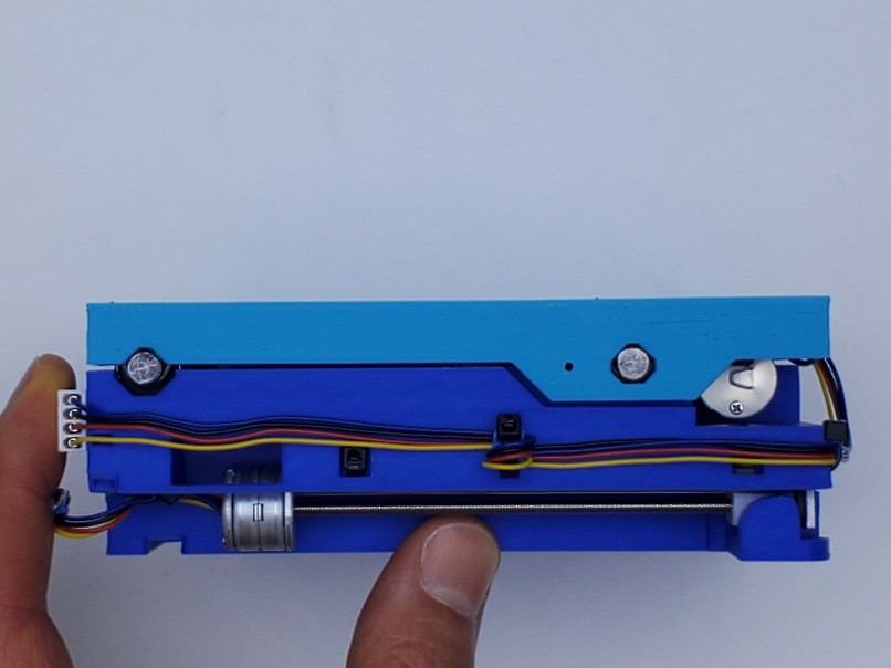
While we're here: a preview of how the rest of this deck-level cable & connector dress will work when we get to it. That's the "wireguide" part on the left. This also shows design detail committed to the 300 mm x 0.1" cable type for the motors (when I started I think that was the only type available). If you have 200 mm motor wiring (do four loosely parallel wires count as a cable?) and you want to fit your motor wiring into this scheme, a short extension with a "DuPont"-like housing will fit where the white connector is but will probably need some filler under it to keep it in line with the constrained mating connector.
Either an option specifically for 200 mm x 2 mm motor wiring or a committed switch to that type might happen.
X axis
The X/top axis goes together pretty much the same way, but simpler because switch wiring is all done. In this part I'll list all the relevant headings from the Y axis, and insert some things that differ. Hopefully that will help track when to check back here while reading there.
like Y axis but...
install bearings
Maybe you already did.
The ties for the lower bearings enter from the sides like this.
install [X] motor
These two ties would have been easier to insert before I put the motor in. But I didn't do that. So I don't know whether or not that would have interfered with installing the motor. I think not but ?.
Secure the motor wires like this.
I've wrapped tape strips around the wires to protect the insulation where ties will land on them. That might be a good idea for the limit switch cables. However it may be hard to mark where the tape should go in some cases like the upper tie for the X cable.
pre-set [X] lower rod
Extend the Y axis for access to the zip tie locations. If they're hard to insert, it may help to bend some backward curl into the ends of the ties.
pre-set [X] upper rods
[X] axis assembly
Pretty much same as the Y axis.
done with that part
Yay!
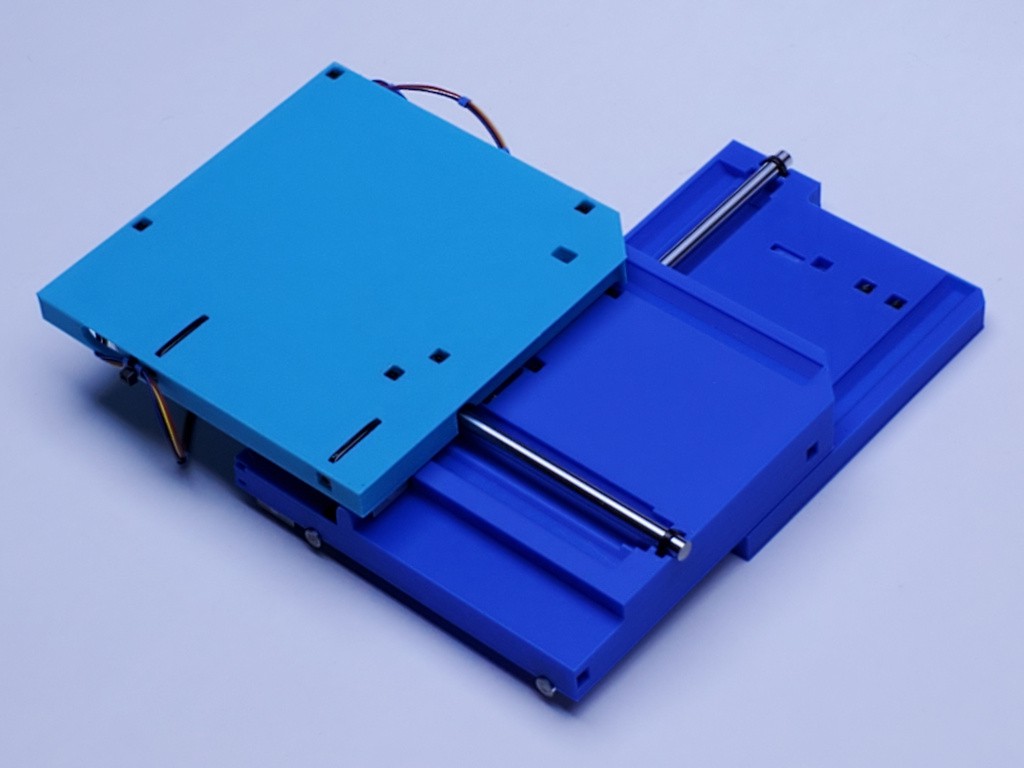
Now you have two unconstrained axes.
From the laser-cut slide context, here are some comments about checking
and
off-axis stiffness (which directly follows the first but here's a label for clarity)
Th text includes some stuff specific to the laser-cut context so you'll have to filter that. The part about testing under load is a little complicated because you have a stack of two axes which makes it harder to support and load just one axis.
The "off-axis" discussion has less context-specific noise.
springs exist again
note: once the springs are in they are vulnerable until adjusted at least pretty close to right. I've made a mid-stream change here to delay installing the springs which I think helps to avoid complexity earlier in assembly, which means I've only tried installing springs after assembly once and didn't take pictures.
install Y spring
I suggest starting with Y because it's easier to see.
It's a little tricky to get the spring in with the screw in place, but doable. I don't have a repeatable method yet. Here's some points:
- there is a hazard of damaging the screw thread while crashing around it with tools. I'll suggest protecting it with e.g. a bit of tape.as well as just trying to not abuse it
- I made a 'recovery tool' from another paperclip by bending a small hook in the end - that helps to pull the spring back out after an unsuccessful attempt to install it
- I used fine needle nose pliers to hold the 90º bend at the end of the moving arm so that I could twist the end as well as move it around, then while holding by that corner put the spring in place with the moving arm lifted up into the wider clearance opening while torquing the perpendicular end down so that the end of the wire at least landed on the drive tab if not actually through the slot. once on the face of the tab it was easy enough to push it toward and into the slot
set initial Y backlash
This is just to get into the ballpark, not to fret minimizing backlash. This protects the spring by getting interacting parts into a "safe" configuration.
To begin with, the backlash adjustment is essentially set to backlash=range of motion. But it doesn't really count as an "adjuster" until it's adjusted down to much less lash.
You should be able to "roll" the leadscrew with your thumb. If the screw does not turn easily, a likely reason is that the backlash adjuster wheel is jammed against the frame at the non-motor end of the screw. Turn the adjuster toward the motor end until there is visible separation between the adjuster and the frame at the not-motor end of the screw.
Roll the screw to move the slider away from the motor a few cm. Expose enough screw between the motor and slider so that you can roll the screw from there.
Roll the adjuster wheel toward the motor to close up the space between the adjuster and the slider.
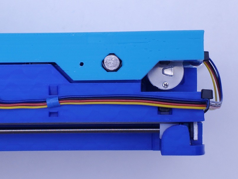
When the adjuster meets the drive tab, it will run into the side of the locking spring. Take care to avoid force on this contact which can bend the spring.
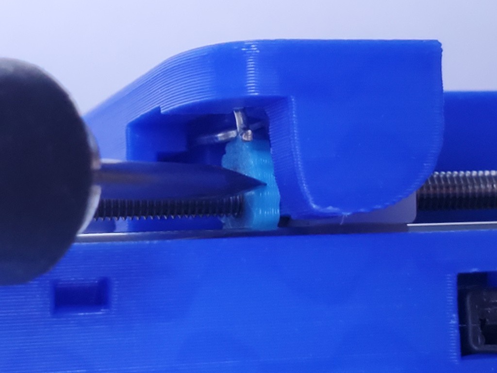
Put a bit of tape over the screw near the adjuster (suggested) and use a small screwdriver or such to compress the moving arm of the spring so that it clears the adjuster. Also keep the tool out of contact with the adjuster. As shown below, the small screwdriver compresses the spring while also avoiding contact with the adjuster.
Now you should be able to roll the screw, which will move the slider, without the adjuster moving on the screw. Roll the screw to move the slider up tight to the adjuster wheel, pinching the slide drive tab between. Release the spring.
(probably not that close to the motor)
If you have brought the slider and adjuster close enough together to keep the spring from slipping off the adjuster wheel, then the spring is protected from being bent. If there is enough slack to allow the spring to slip off the screw, then repeat compressing the spring to move the slider without moving the adjuster to close up the gap.
If you can also roll the leadscrew freely so that the slide moves, then you're done with this.
If the screw is jammed, then the adjuster is too tight. Using a small screwdriver or anything that can get traction on the edge of the adjuster wheel, turn it several notches ccw to liberally open up the adjustment to allow free motion.
However slowly, you should be able to move the Y axis by rolling the leadscrew. If you have a motor driver set up already, you should be able to operate the full range of the axis -- a little more than 75 mm -- and read the limit switch.
You might want to close up the slide for convenient handling -- although it is some inconvenience to do so without power.
set initial X backlash
Set an initial backlash adjustment for the X axis in the same way.
For the X axis, you will have to work closer to the not-motor end in order to keep enough screw exposed to be able to roll it manually.
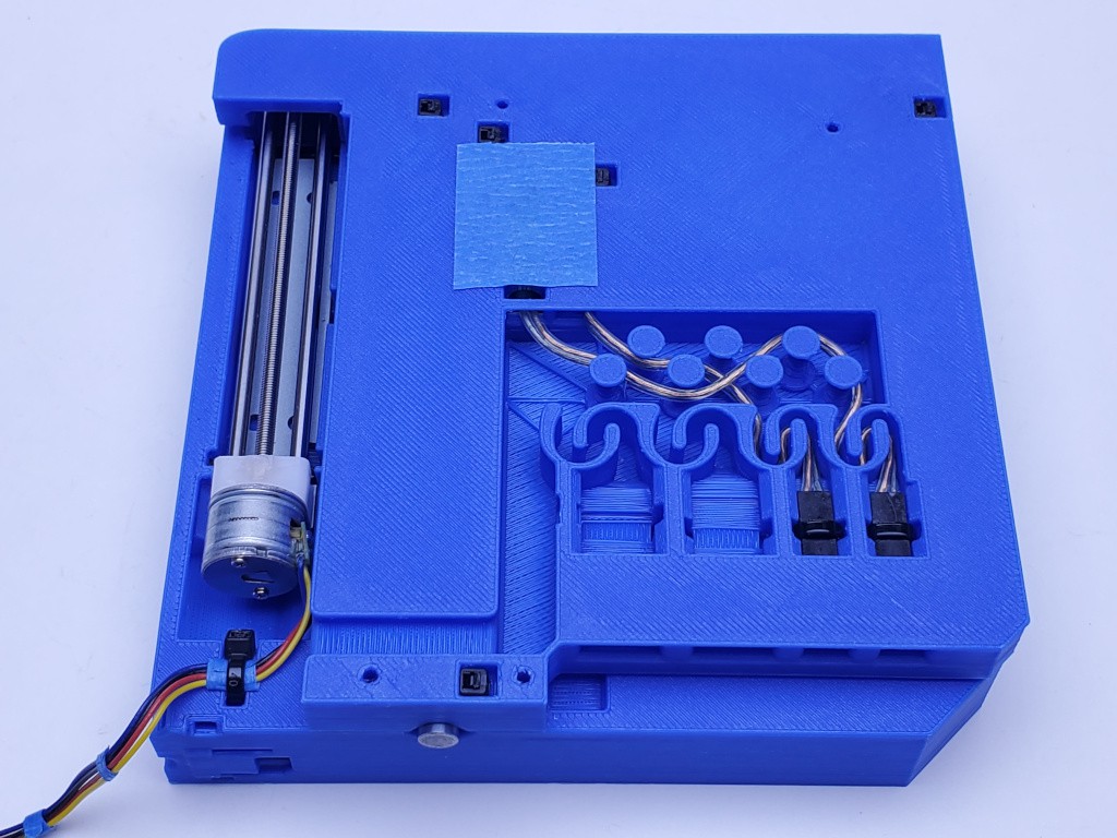
Assembled!
That pretty much completes mechanical assembly of the X-Y stage.
If you have electronics ready, you should be able to operate the axes, read limit switches, home it, and set soft limits. The range of motion should be a smidge over 75 mm -- enough to safely use 75 mm.
Also, you'll need power to close up the last finger-width of the X axis.
electronics and Grbl config
motor current
microstep level
steps/mm = (40 x microsteps)
xxxx speed (conservatively)
yyyy accel
motor direction
homing
soft limits
dress motor wiring
If managing the motor wiring, which moves, isn't a problem in your application, then you may have no need for fancy cable dressing. I wanted the wiring in close, snagless, tied down, disconnectable, and not using deck space around the back-left corner. The limit switch cables are already internal. This part describes dressing the motor wiring.
The X motor will need an extension. The middle part has features specifically for securing that connection to the 300 mm x 0.1" type of motor wires. 200 mm wires connecting to a longer extension can follow the same path with improvised tie-down details.
If you have 200 mm x 2 mm motor wires, and haven't printed parts already, ping me for STLs with different features that might, or at least are intended to, work better for the 200 mm wires.
For 300 mm cables, make up an extension from 35 cm length of wire for a finished length around 33.5 cm between connector housings.
For 200 mm motor wires, you'll need a longer extension but I don't know how much longer. And a different connector on the motor end.
I've wrapped small bits of tape around the motor wires where they are held by zip ties to protect the wires. It seems like a good thing.
Anyhow... getting started:
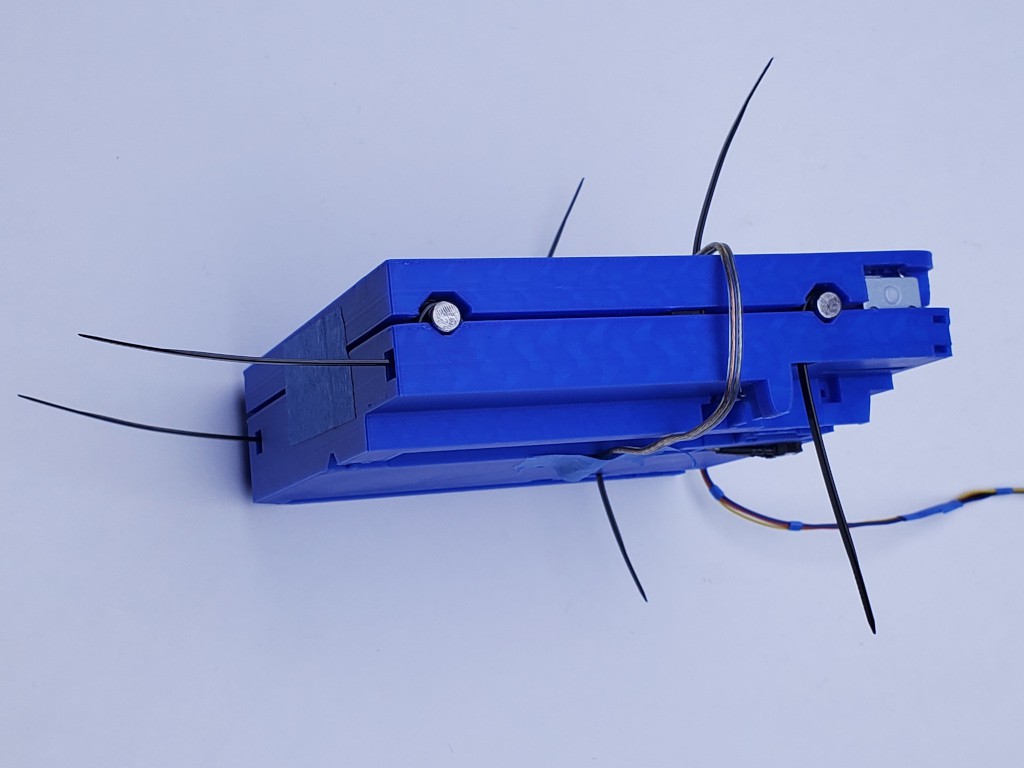
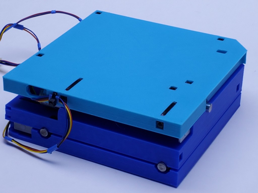
Tie the X motor wire at the corner of the middle part so that it makes a relaxed 180º bend from horizontal at the upper level to horizontal at the middle level. It should look like this with the axis closed:
And the same bend upside down when the axis is fully extended:
Run the wires down the side of the middle part with enough tension to pull out slack, and wrap where they pass the zip tie cutout on that side.
Uh, I didn't take a picture of this detail for attaching the connector.
Or a closeup of the connector...
The connector has a pair of "blade"-ish projections on one side. They fit in the highlighted depressions.
While holding the connector in that position, draw the wires toward the motor from there and wrap again where they pass the zip tie point.
Insert a tie (easiest to go in the bottom & out the top -- not super clear in the pic) and loop the wires to capture the two wrapped points.
Connect the X motor extension and secure both the motor wire connector and the extension with a tie. Ties fits in at the top and out the bottom.
Insert another tie at the corner (in at top out at bottom) and capture both the X extension and the Y motor wires so that they come out the tie together along the side of the middle part.
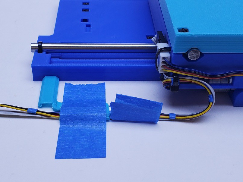
Fully extend the Y axis for access to the corner of the bottom part. Tape the "wireguide" part into position relative to the bottom part. Or, if you've already screwed down the axes, then go ahead and screw down the wireguide too.
Run both motor cables under the parallel part of the wire guide and adjust so that they lay together and make a relaxed 180º bend from the middle part to the surface. Tape the wires together right at the edge of the wire guide to mark that position.
Free the wire guide and tape it to the motor wires in the same position that you just marked.
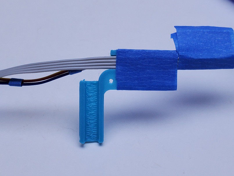
Bend the wires 90º and tape them into the perpendicular part of the wire guide.
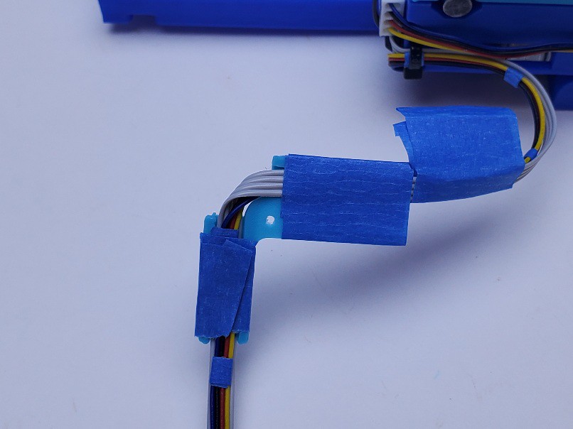
Now lay the wires into the channel across the bottom of the bottom part with the wire guide in position and tape the wires in place there. Turn the wires up the channel.
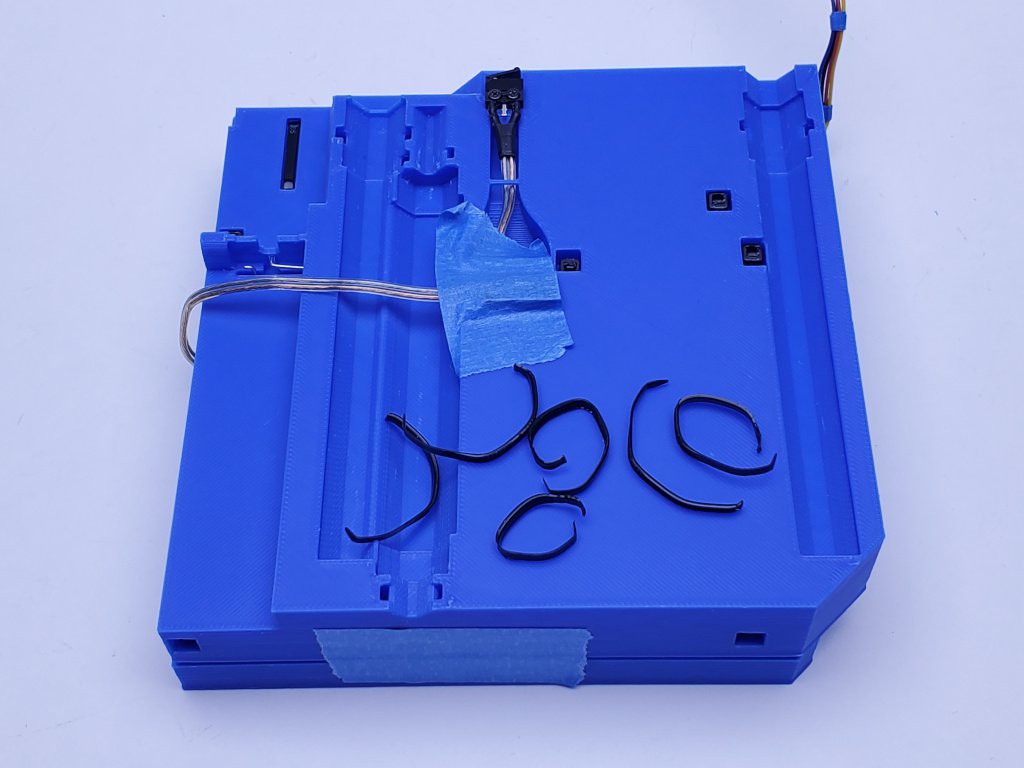
The zip tie arrangement for the Y motor connector (the differently shaped cavity nearest the wire entry) is a little more obscure than others. It starts like this:
And closes up like this:
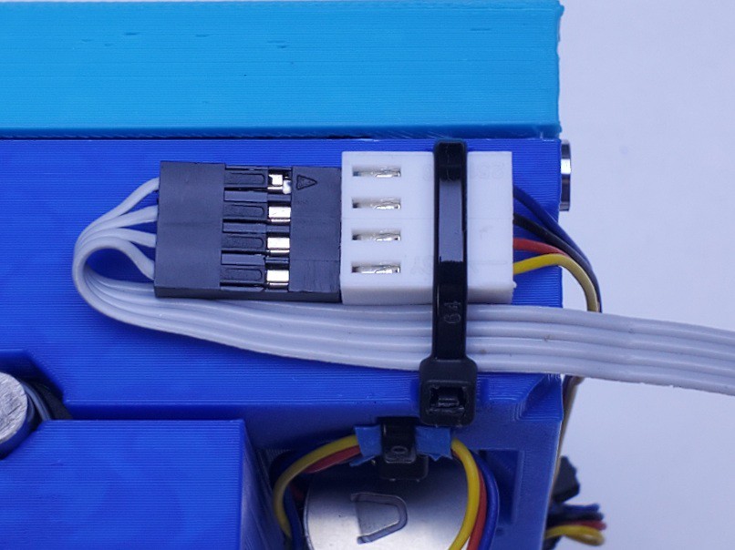
Anchor the connectors and dress the wires the same way as for the limit switches. The Y motor connector fits in the first space and a 4p DuPont-type connector the the X motor extension fits in the second space.
 For convenient handling, a neatly placed piece of tape holds the wires in the channel. In this pic, I left a little extra tail on the Y connector zip tie which also helps to keep the wires up in the channel. Just opportunistic; not necessary.
Now you can screw down the bottom part of the X+Y stack and the wireguide. I've attached them to a intermediate deck that attaches to my machine frame, in part because I keep changing the mounting screw pattern and put lots of holes in the previous frame. You maybe won't have that problem.
Again with Y axis closed up.
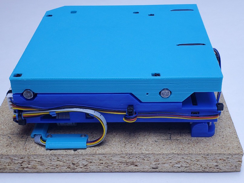
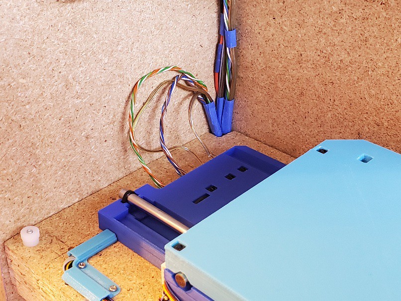
Installed and connected in the frame that is the other aspect of this project. Easy in & out without disturbing the wires lead up from below, and empty space that might turn into another frame shrink (or not considering other priorities for this project in finite time).
backlash tuning
Tighten until jammed, then back off 1 notch at a time until it moves. Might prefer another notch looser for less drag. Should be able to get unloaded lash under 0.025 mm / 0.001" without disabling drag.
disassembly
one axis at a time.
Before splitting the X axis, clip ties securing the X motor cable to the middle part of the axes and unplug the motor cable from its extension.
Before splitting the Y axis, cut the X axis limit switch connector loose and disengage the cable from the serpentine & peg field.
While splitting the Y axis, cut the tie securing the X axis limit switch cable in the bottom part and pull the cable out from the bottom part to separate the halves.
To split an axis: using something thin enough to fit between the two parts, push the interior rod ends outward until either they're pushed out from under the interior zip ties, or there is enough exposed rod out the other side to grip and pull.
Unless you are sure that you will not want to re-assemble the axis, pull rods out far enough to clear bearings without pulling them entirely free of the remaining tie. There is more margin if you can extend the slide and less margin if you are splitting a closed-up slide.
If you are sure that you will not want to re-assemble the axis, pull the rods out completely.
Separate the slide halves.
reassembly
run the sliders to the motor ends of the screws and backlash adjusters to the other ends.
cut and replace the interior rod end ties and pre-set them as above.
assemble as above.
to split and reassemble the X axis only, extend the Y axis for access to the lower X interior rod end tie.
to split and reassemble the Y axis only, extend the X axis for access to the interior end tie for the motor-side upper rod via hole through the top part (in theory; unproven)
Discussions
Become a Hackaday.io Member
Create an account to leave a comment. Already have an account? Log In.