 deqing
USB PD sink example for CH552 and CH549
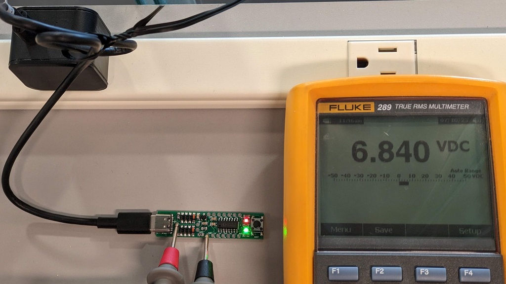
This project uses a general-purpose microcontroller (CH552) to receive and send USB PD signals over CC lines without any phy peripheral. An analog comparator and a timer receive the signal. A GPIO with clamping diodes transmits the signal. The sample code makes CH552 act as a USB PD sink controller and requests a programmable voltage from a PD/PPS charger.
This method can also be ported to any general-purpose microcontroller with comparator, ADC and digital output.
If a simpler circuit is desired, a CH549 can also be used. The code will utilize the internal voltage reference and low voltage output capability.
##How it works:
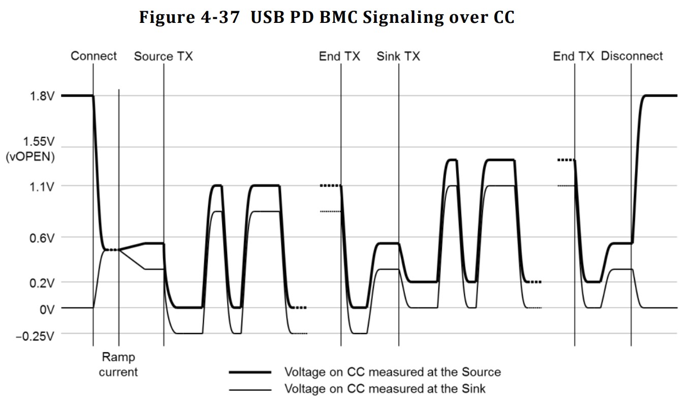
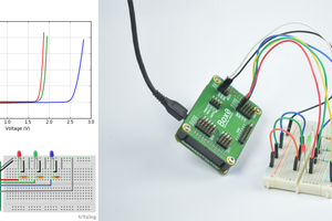
USB PD uses BMC (Biphase Mark Code) over the CC lines in the USB Type-C connector to exchange data between the source and sink devices. However, the maximum voltage of the communication is about 1~1.2V, so it can not directly interface with the digital IO of a microcontroller.
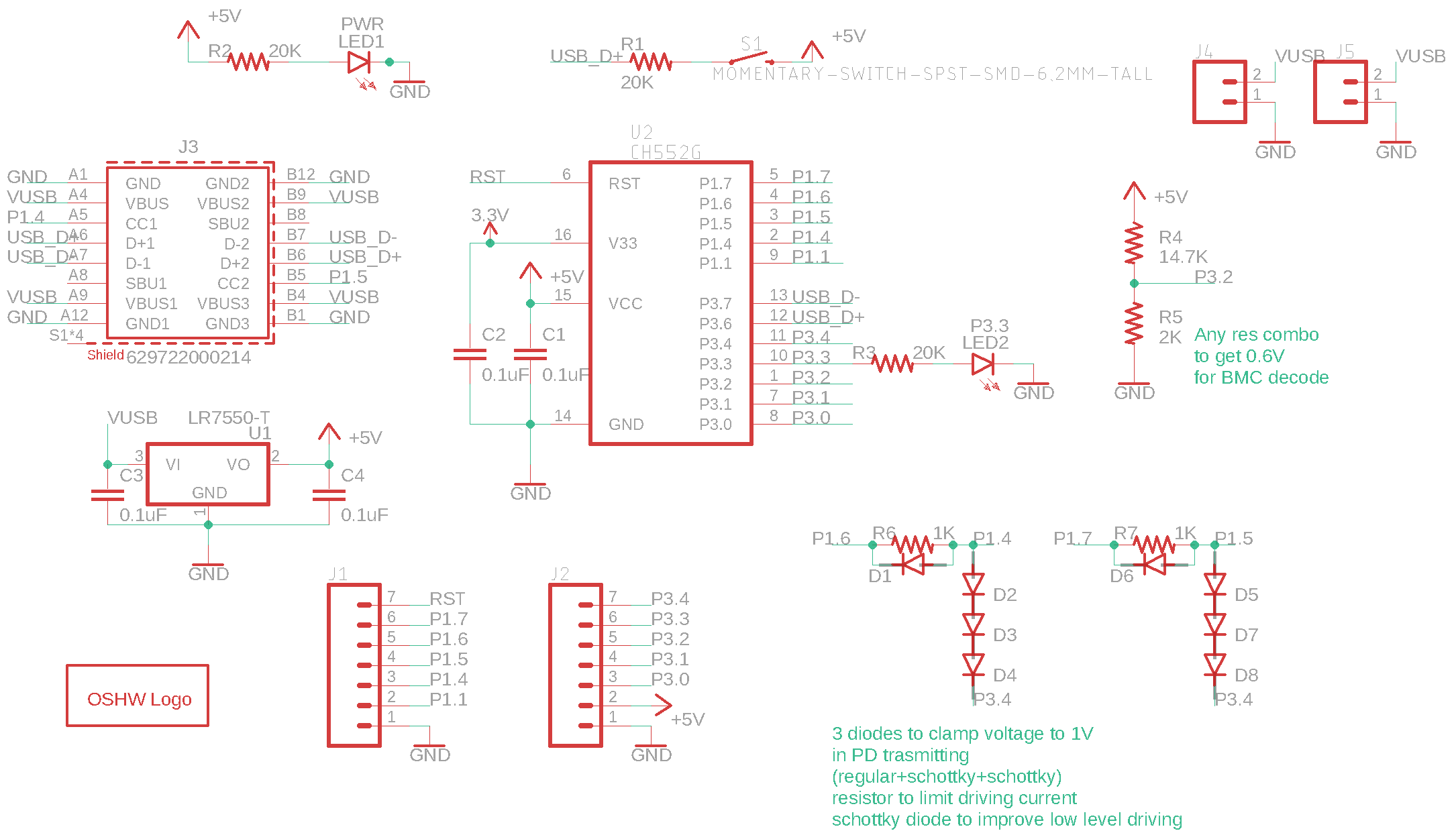
For input, an analog comparator compares the signal with a 0.6V reference to convert the signal into a digital one. The software uses a timer to measure the timing distance between transitions and decode the Biphase Mark Code back to binary.
For output, the output voltage is clamped to 1V with a 1K resistor, a regular diode and two schottky diodes. The cathode of the series of diodes connects to anthor GPIO to make the clamping controllable. So any digital output will be clampped to 0~1V output.
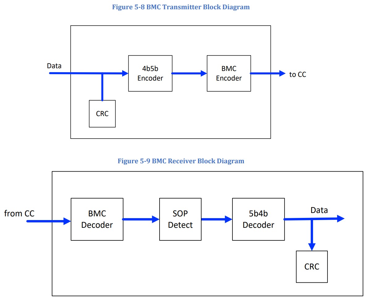
After the the signal got decoded from BMC. The software will look for the preamble of alternating 1, 0. Once the preamble ends, the software will record the binary in groups of 5 bit. After the signal ends, we check the SOP, do 5b4b decoding and check the CRC. If everything is valid, we parse the data packet with USB PD protocol.
Sending the data back is similar, we generate CRC, encode the data with 4b5b, add SOP and EOP, then we send data back with BMC encoding.
 Kuldeep Singh Dhaka
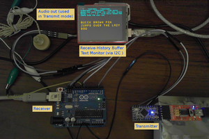
 Dilshan Jayakody
 kevarek