 Aaed Musa
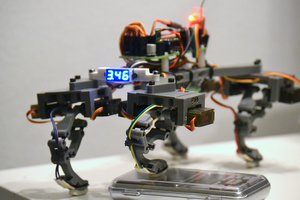
- 4 Month Build
- Total Cost: $3,300
- Total Weight: 29.6lbs (13.43kg)
- Weight of 3D Printed Parts: 9.98lbs (4.53kg)
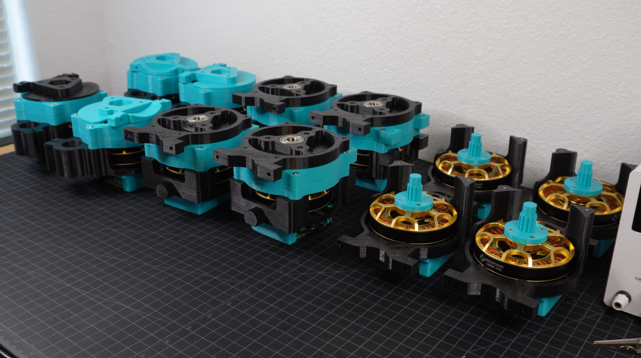
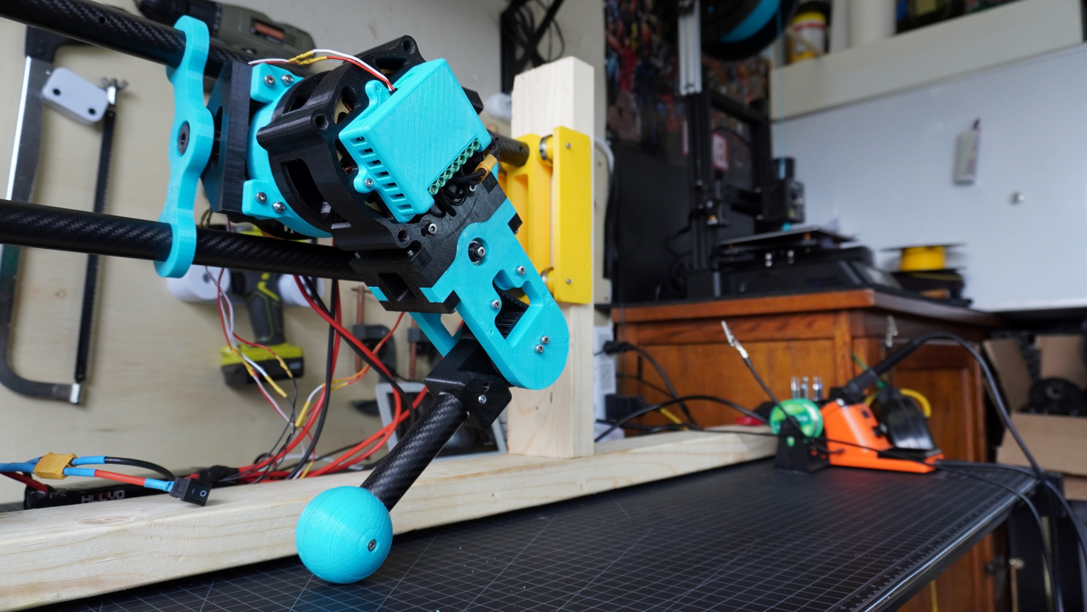
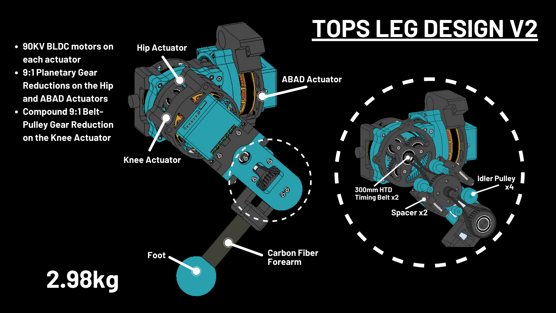
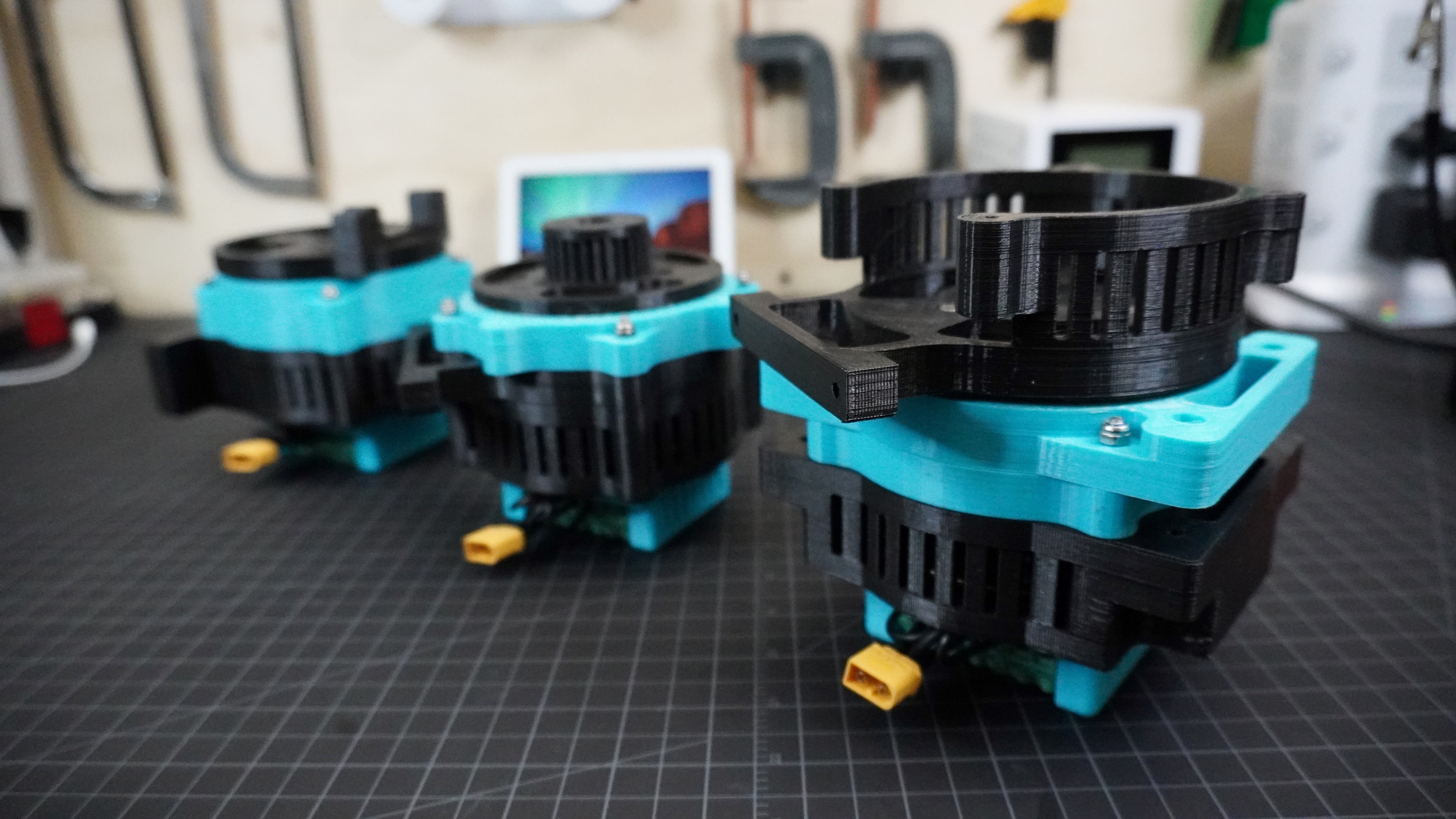
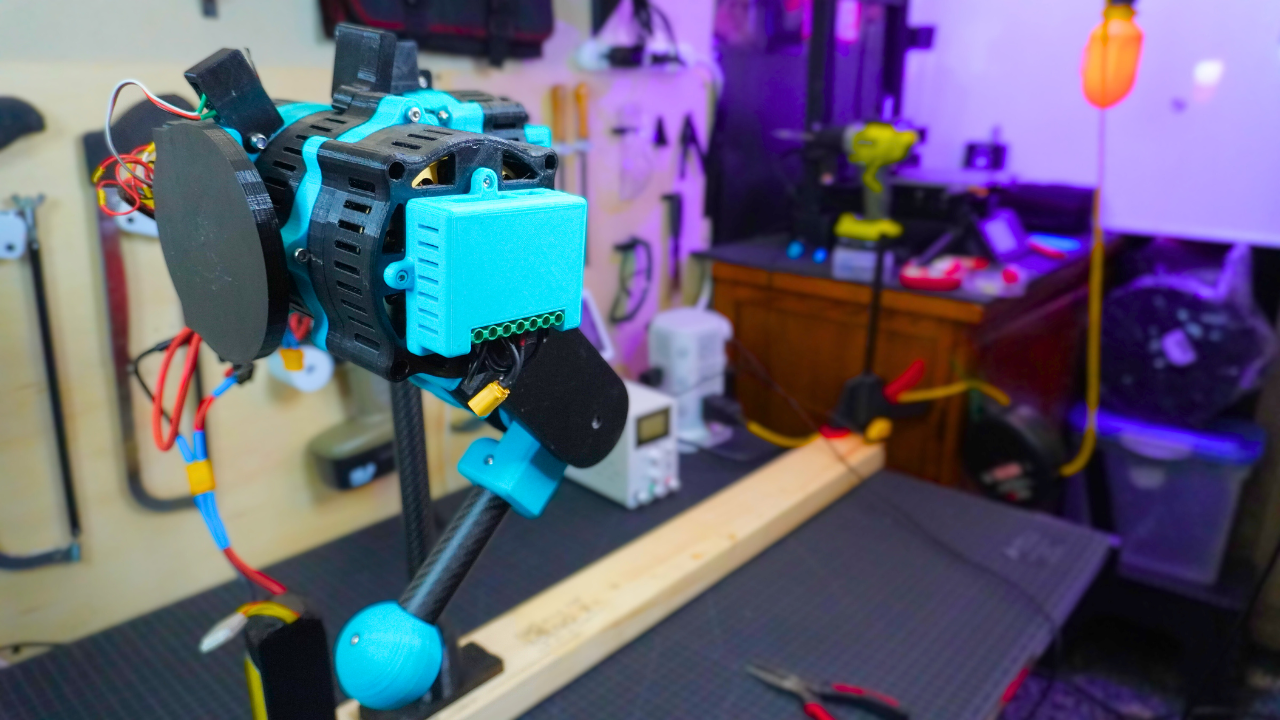
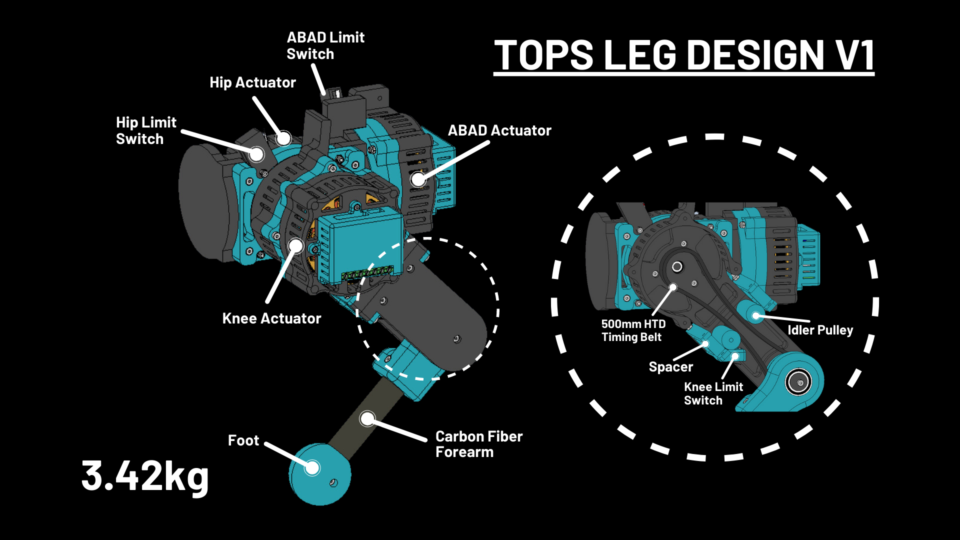
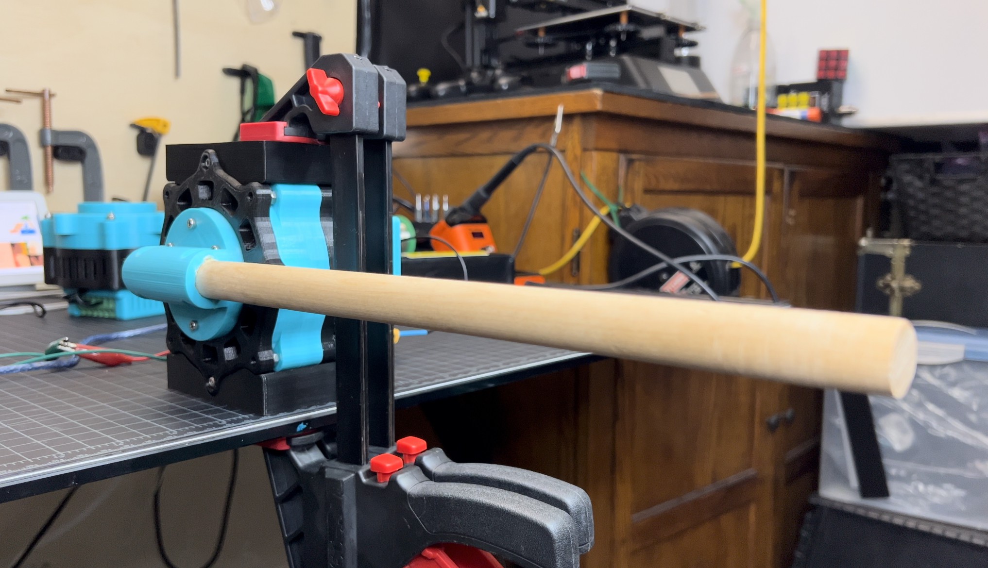
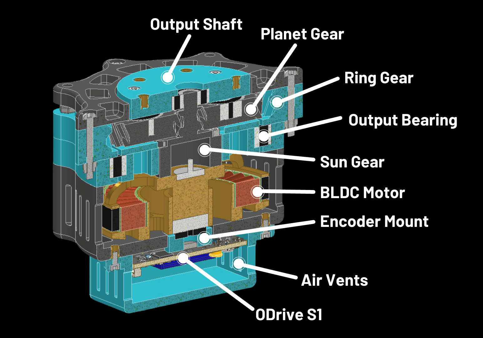
- 12x Custom QDD actuators
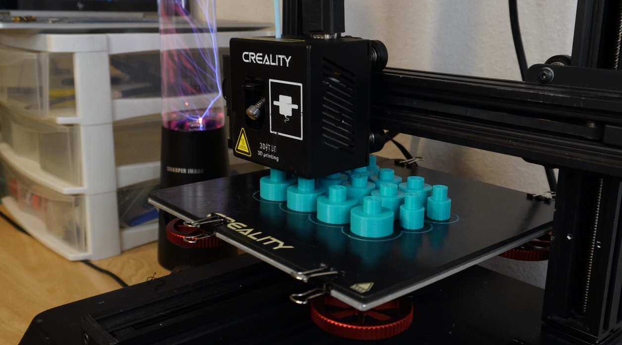
- 3D printed 9: 1 planetary gearbox
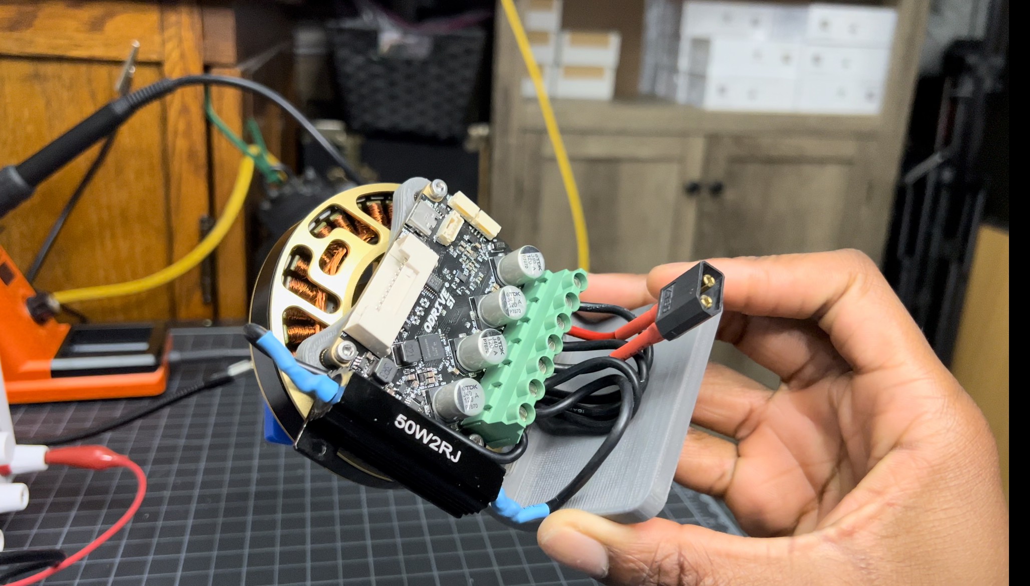
- 90KV brushless motor
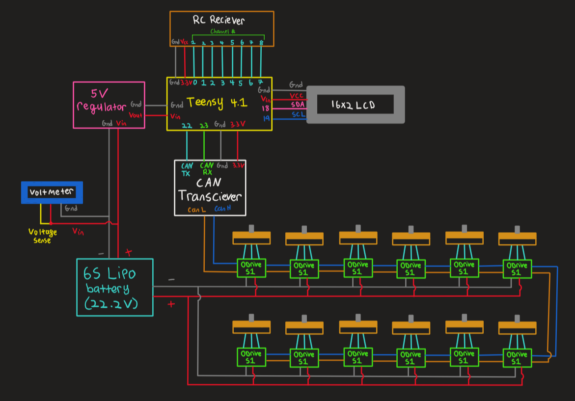
- ODrive S1 FOC Controller Carbon Fiber Frame
- 30A Silicone Feet
- 6S 5200mah Lipo Battery
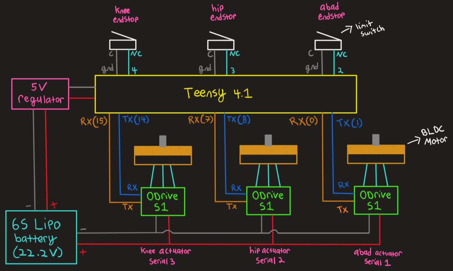
- Teensy 4.1 Microcontroller
0%
0%
Become a Hackaday.io member
Already have an account? Log in.
Just one more thing
To make the experience fit your profile, pick a username and tell us what interests you.
Pick an awesome username
hackaday.io/
Your profile's URL: hackaday.io/username. Max 25 alphanumeric characters.
Pick a few interests
Projects that share your interests
People that share your interests


 Leo Vu
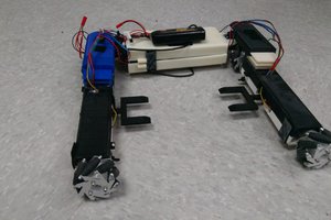
 Yannis
 Carl Bugeja
Also I believe I found an issue with "Plane_Carrier_Top(1)" for ab-ad, it overlaps with 2 different models from what I can tell.
I'm very excited to have my first leg built and thanks for this great project!