 Arduino Enigma
This project is licensed under (CC BY-SA 4.0) https://creativecommons.org/licenses/by-sa/4.0/
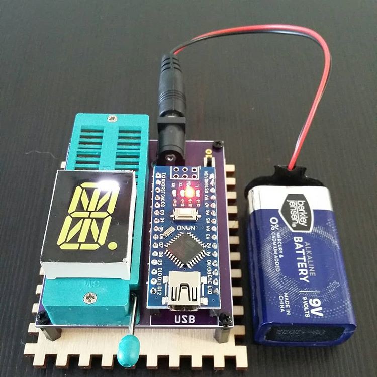
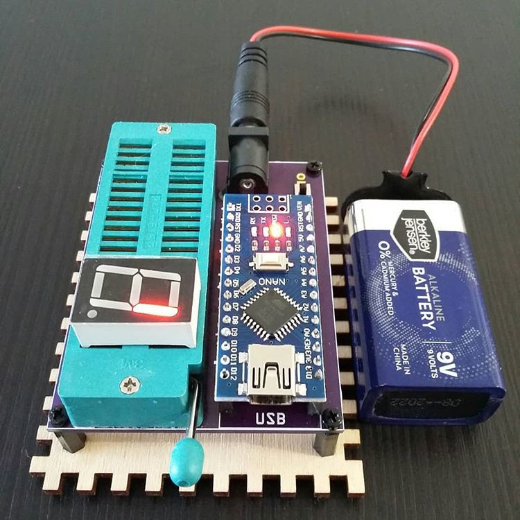
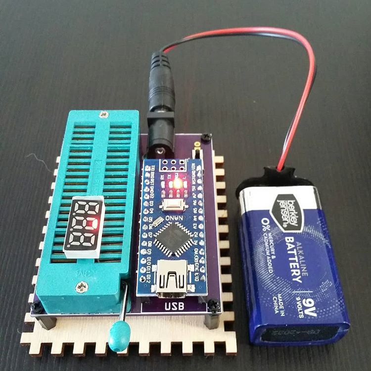
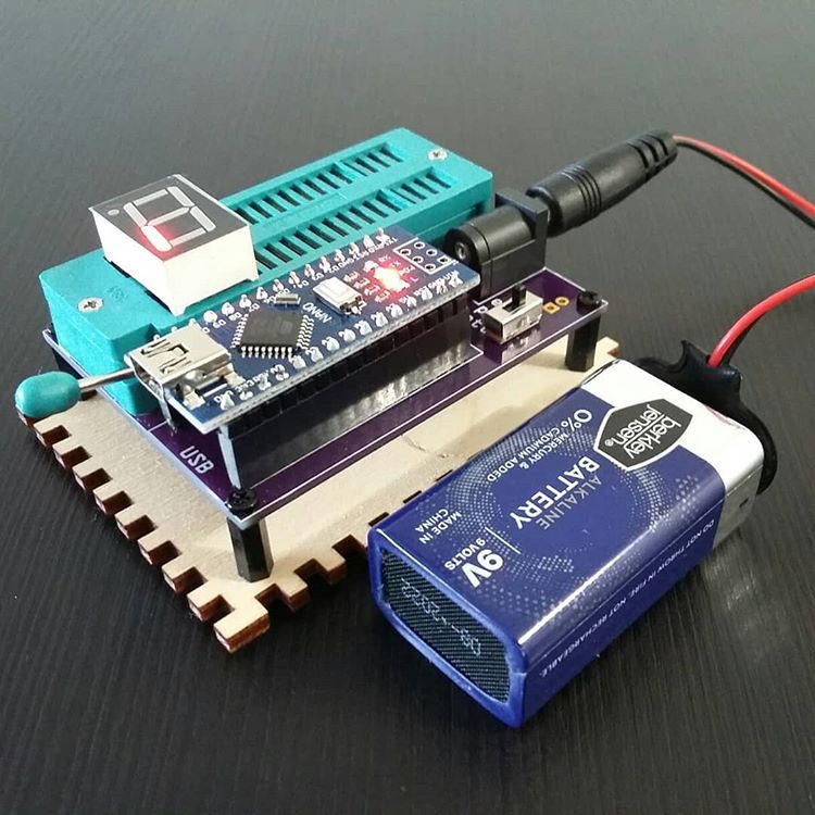
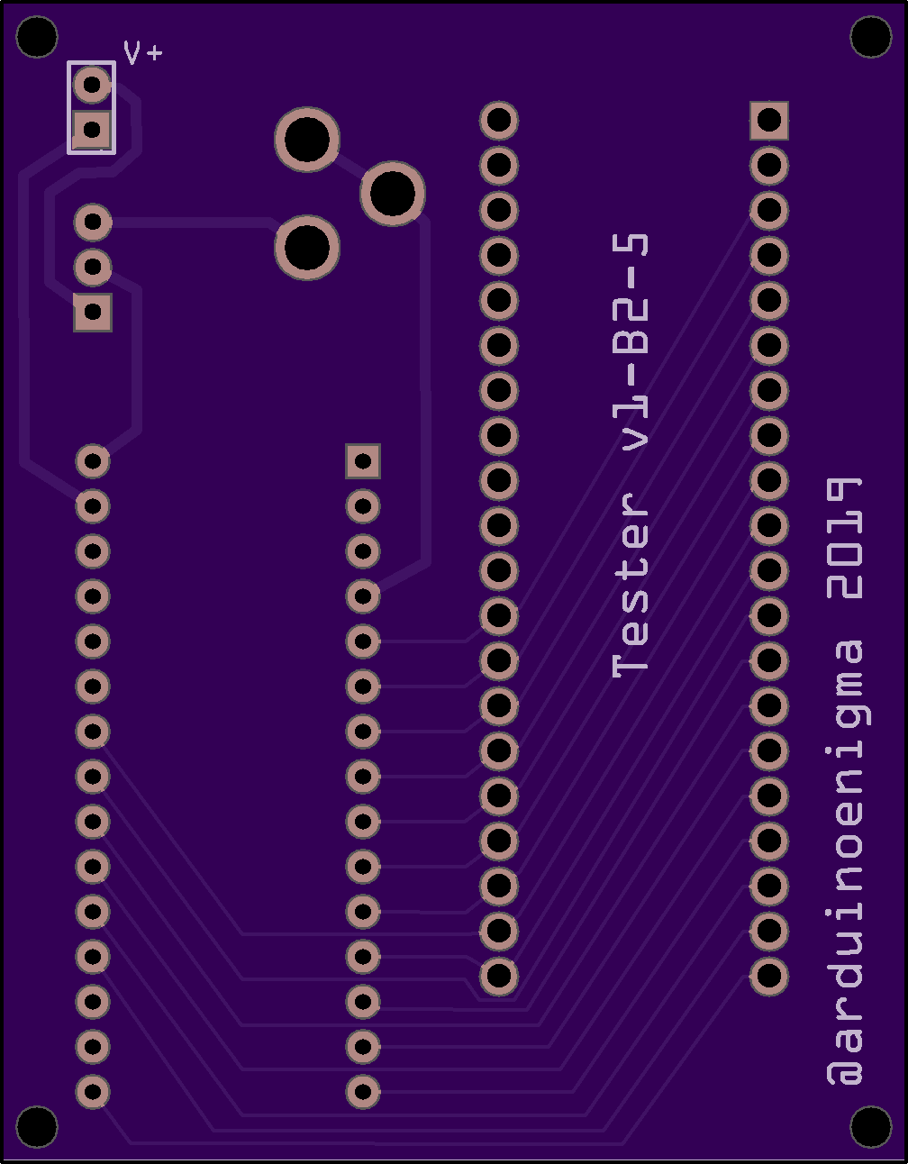
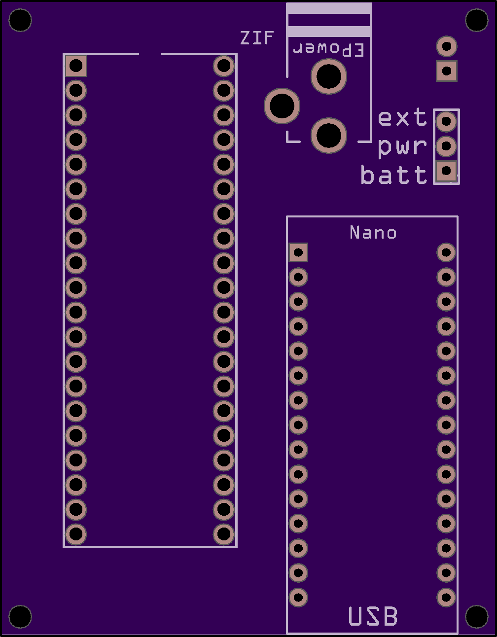
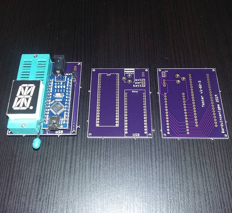
When creating three different Enigma Simulators and a Sinclair Scientific Calculator, one works with many LED displays. There is a small percentage of defective displays and it is good to identify them before soldering or sending them out to customers. Thus the necessity for an LED tester was born.


 SUF
SUF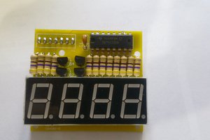
 Clovis Fritzen
 Patrick Hickey