Close
0%
0%

LED Lab Lamp Mod

Modification of the lamp with a magnifying glass to illuminate the workspace. The device emits warm and cold light.

Public Chat
Similar projects worth following
280 views
0 followers

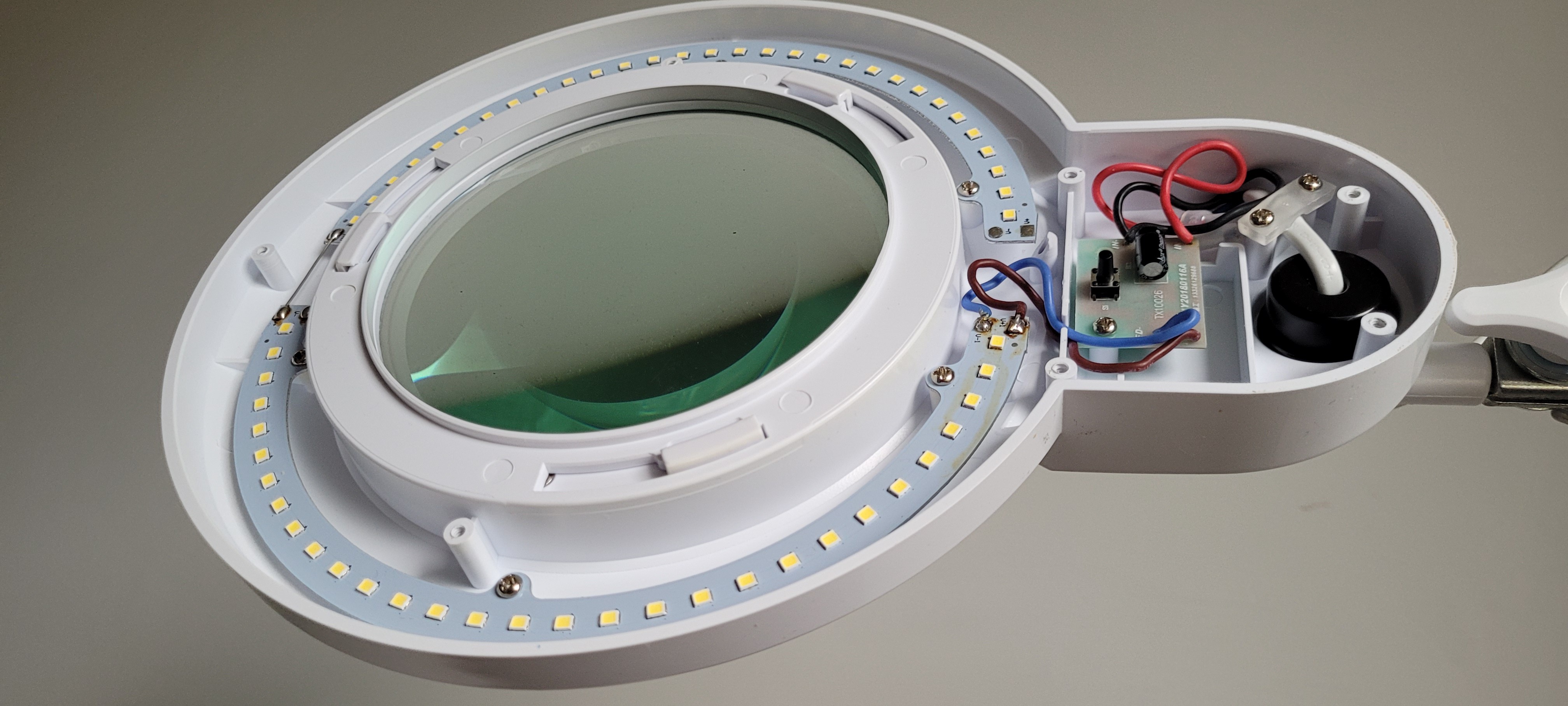
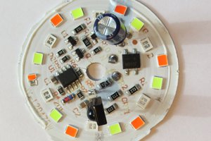
The purpose of the project is to modify the lamp with a magnifying glass model 9006LED-127. The device is available, among others, on the Polish market (European Union). By default, the lamp is equipped with lighting consisting of 60 LEDs. The color temperature of the emitted light is about 5500K. In addition, the device has three modes of light brightness control.

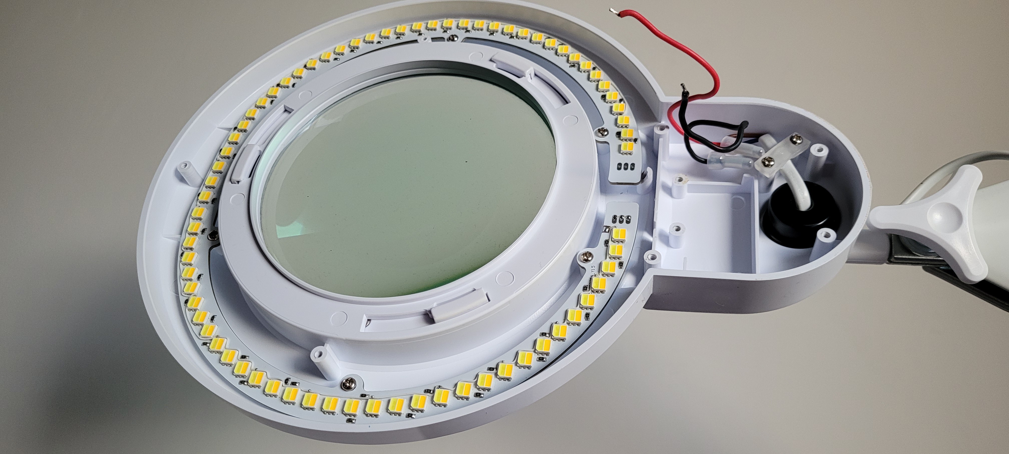
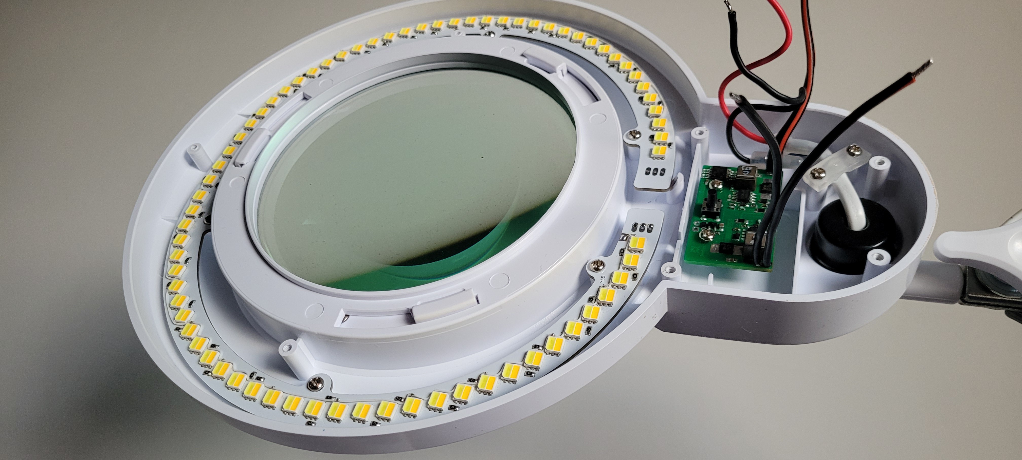
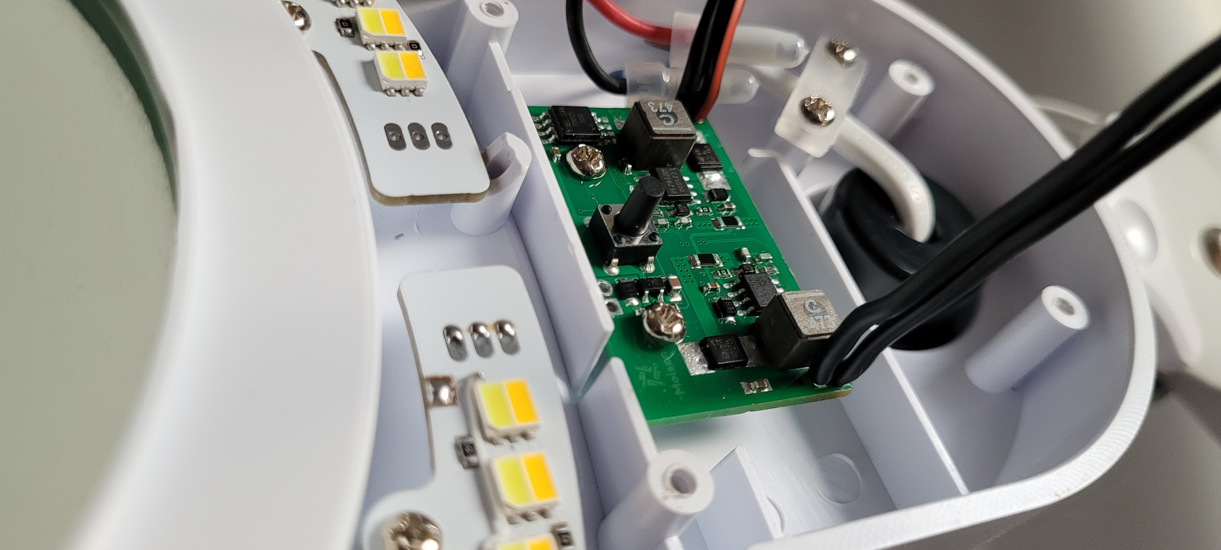
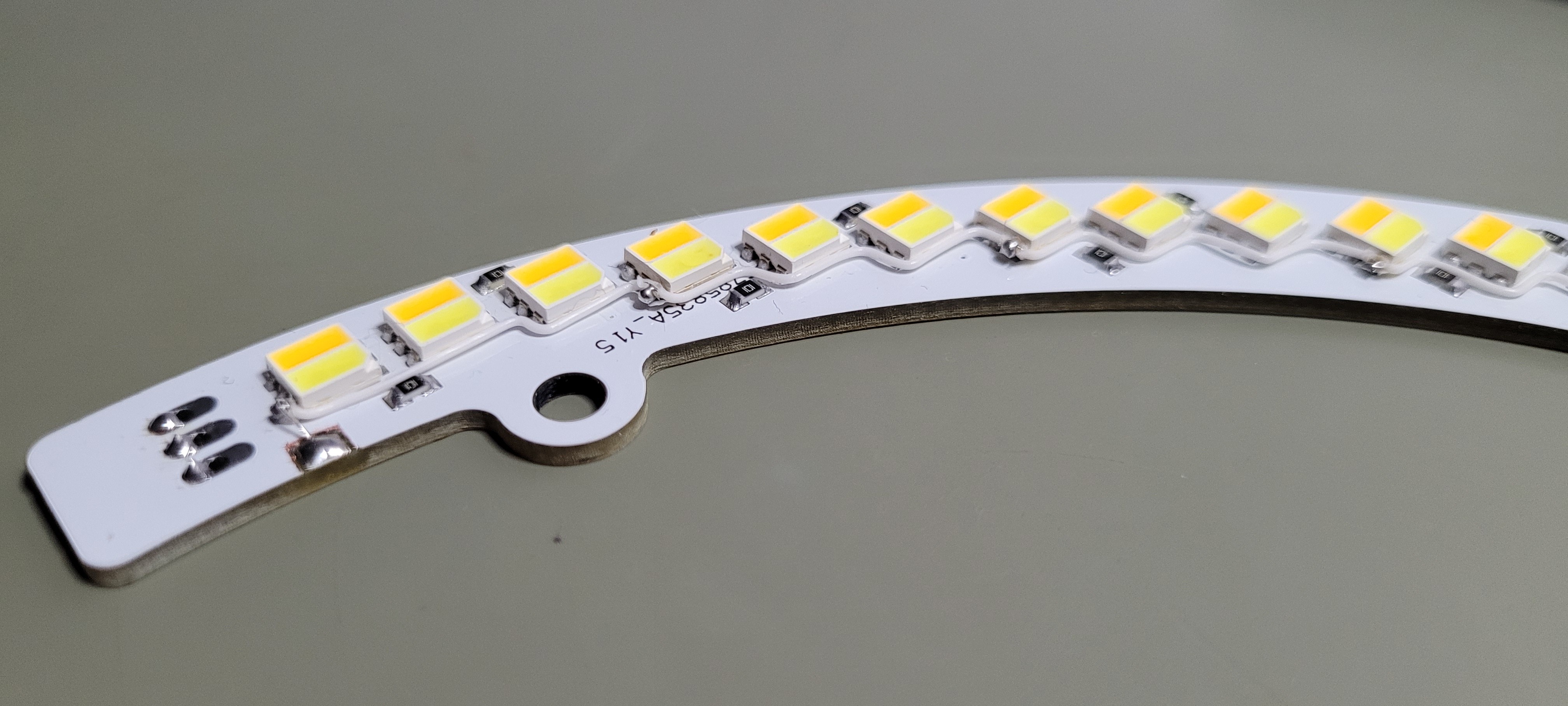
The modification involves replacing the LEDs with double LEDs in a single chip. The dual LEDs offer warm and cold color temberature of the emitted light in a single SMD 5050 chip. As a result, the device will be able to emit cold, warm and neutral (cold+warm) light.

The color temperature of the emitted light has a significant impact on our mood. Staying (office, store windows) in rooms illuminated with cold light (4500K-5000K), the human sense of sight sharpens and the person becomes stimulated. On the other hand, staying in the environment of warm light (2800K - 3100K) we become more relaxed.

Datasheets.zip

Documentation files.

x-zip-compressed - 3.22 MB - 08/26/2023 at 11:56

Download

Hardware.zip

Source files of the Hardware Layer.

x-zip-compressed - 502.94 kB - 08/26/2023 at 11:55

Download

Firmware.zip

Hex files with firmware for ATtiny25.

x-zip-compressed - 1.21 kB - 08/26/2023 at 11:55

Download

  • Final

    Grzegorz08/26/2023 at 11:45 0 comments

    I resolved issue with mode 1 where both channels working with 100% brightness.

    I checked the current efficiency of the original power supply and it turned out that the current efficiency is 0.55A and the voltage Vout = 18.5V. Both channels require about 0.65A of current when lit with maximum brightness. I reduced the PWM fill value for modes 1, 2 and 3. Now the flickering effect does not occur. The whole thing looks pretty good. Pleasant warm color of light will certainly make long winter evenings more pleasant.

    The device is now in the phase of long tests of 2-3 months. Perhaps in the meantime I will add some improvements to the software.

  • Assembly

    Grzegorz08/26/2023 at 09:46 0 comments

    Now it's time to assemble the driver and LEDs in the case. First, I dismantle the original parts from the case. Eight screws in total. Six screws for the LED panel and two screws for the controller.

    However, I still had to solve the problem of audible noise before assembling the components in the enclosure. In the end, it turned out that the source of the audible noise in the form of high-frequency sound (about 11-16 kHz) was the power coils. I decided to replace the power coils for both channels. I changed the value from 22uH to 47uH. I used a dedicated coil for the LED5000 chip, which was designed by Coilcraft. It is a model XFL6060-473. After installing the coils and adjusting the capacitance values of the capacitors in the LC circuit, the annoying sounds disappeared.

    The new panel fits perfectly into the mounting holes:

    The controller board takes up a bit more space than the original controller board. In this case, it's not a problem.

    After mounts all pcbs in housing I soldered connecting wires. Two wire for the Warm Channel, Cold Channel and power supply. Total six wires.

    First launch in housing. Not everything work perfectly. First mode where brightness of the warm and cold leds are set to 100% not working. 

    The LEDs are not light continuously. I observe the diodes blinking with a period of about 0.5s on both channels. It may be a problem with the current efficiency of the power supply. During the prototyping of the boards, I powered it from an external laboratory power supply. I need to debug.

    The other modes work exactly as I assumed. On a short video presentation you can see the effect:

  • Firmware v1.0

    Grzegorz08/25/2023 at 09:51 0 comments

    First version of the firmware is ready and deployment on ATtiny25. After upload firmware to MCU everything looks good. Now I will assembly everything together and testing.

    Below I publish first version of the firmware.

    /*
     * File:   main.c
     * Author: Grzegorz Wozny
     *
     * Created on 25 July 2023, 11:51
     */
    
    #include <avr/io.h> 
    #include <avr/interrupt.h>
    #include <util/delay.h>
    
    #define F_CPU 8000000UL
    #define DIM_CH1 DDB0
    #define DIM_CH2 DDB1
    #define IC_CH1 DDB4 // Warm
    #define IC_CH2 DDB2 // Cold
    #define BUTTON DDB3
    
    int cnt = 0;
    
    int main(void) {
        // Fast mode PWM
        TCCR0A |= (1<<WGM01)|(1<<WGM00)|(1<<COM0A1)|(1<<COM0B1);
        TCCR0B |= (1<<CS00);
        
        // Enable LED5000 IC's
        DDRB |= (1<<IC_CH1);
        DDRB |= (1<<IC_CH2);
        PORTB |= (1<<IC_CH1); // Disable Channel 1
        PORTB |= (1<<IC_CH2); // Disable Channel 2
        
        // Make PWM pins outputs
        DDRB |= (1<<DIM_CH1);
        DDRB |= (1<<DIM_CH2);
        
        OCR0A = 0; // CH1
        OCR0B = 0; // CH2
        
        for(;;)
        {
            if ( !(PINB & (1 << BUTTON)) )
            {
                _delay_ms(20);
                if ( !(PINB & (1 << BUTTON)) )
                {
                    cnt++;
                    _delay_ms(20);
                }
            }
            
            switch (cnt)
            {
                case 1: // 100% Brightness for Warm and Cold Channel
                    PORTB &= ~(1<<IC_CH1); // Enable Channel 1
                    PORTB &= ~(1<<IC_CH2); // Enable Channel 2
                    OCR0A = 255;
                    OCR0B = 255;
                    break;
                case 2: // 65% Brightness for Warm and Cold Channel
                    PORTB &= ~(1<<IC_CH1); // Enable Channel 1
                    PORTB &= ~(1<<IC_CH2); // Enable Channel 2
                    OCR0A = 145;
                    OCR0B = 145;
                    break;                
                case 3: // 25% Brightness for Warm and Cold Channel
                    PORTB &= ~(1<<IC_CH1); // Enable Channel 1
                    PORTB &= ~(1<<IC_CH2); // Enable Channel 2
                    OCR0A = 50;
                    OCR0B = 50;
                    break;  
                case 4: // 100% Brightness for Warm Channel
                    PORTB &= ~(1<<IC_CH1); // Enable Channel 1
                    PORTB |= (1<<IC_CH2); // Disable Channel 2
                    OCR0A = 255;
                    OCR0B = 0;
                    break;                 
                case 5: // 65% Brightness for Warm Channel
                    PORTB &= ~(1<<IC_CH1); // Enable Channel 1
                    PORTB |= (1<<IC_CH2); // Disable Channel 2
                    OCR0A = 145;
                    OCR0B = 0;
                    break;
                case 6: // 25% Brightness for Warm Channel
                    PORTB &= ~(1<<IC_CH1); // Enable Channel 1
                    PORTB |= (1<<IC_CH2); // Disable Channel 2
                    OCR0A = 50;
                    OCR0B = 0;
                    break; 
                case 7: // 100% Brightness for Cold Channel
                    PORTB |= (1<<IC_CH1); // Disable Channel 1
                    PORTB &= ~(1<<IC_CH2); // Enable Channel 2
                    OCR0A = 0;
                    OCR0B = 255;
                    break;
                case 8: // 65% Brightness for Cold Channel
                    PORTB |= (1<<IC_CH1); // Disable Channel 1
                    PORTB &= ~(1<<IC_CH2); // Enable Channel 2
                    OCR0A = 0;
                    OCR0B = 145;
                    break;                
                case 9: // 25% Brightness for Cold Channel
                    PORTB |= (1<<IC_CH1); // Disable Channel 1
                    PORTB &= ~(1<<IC_CH2); // Enable Channel 2
                    OCR0A = 0;
                    OCR0B = 50;
                    break;                  
                case 10: // 0% Brightness for Both Channel. Disable ICs.
                    cnt = 0;
                    PORTB |= (1<<IC_CH1); // Disable Channel 1
                    PORTB |= (1<<IC_CH2); // Disable Channel 2
                    OCR0A = 0;
                    OCR0B = 0;
            }
        }    
    }
    

  • Firmware

    Grzegorz08/08/2023 at 06:54 0 comments

    I am going to the development phase of the software. The target ultimately will be the ATtiny25 microcontroller. The ATtiny microcontroller is powered by 5V and also puts out such logic on its IO ports.

    To prepare the software, I will use the MPLAB X IDE environment and the USBAsp programmer. I will upload the compiled program to an HEX file using the avrdude.exe program.

    Working in progess...

  • Tests of both channels

    Grzegorz08/08/2023 at 06:50 0 comments

    Hardware modifications were made for the cold channel. The Vcc signal on the LEDs board was separated. Now it was time to test the whole solution using an external PWM signal generator. In our case, as before, it will temporarily be an Arduino Nano. The target control software will be uploaded to the Attiny25 MCU.

    I connected the Led to the controller and prepared a sketch of the target application. The Arduino generates PWM signals according to the selected mode.

    The circuit works as expected. I can independently control the brightness of the LEDs on both the cold and warm channels.

    I still need to go back for a while to adjust the value of the output capacitor C19 for the cold channel. Perhaps C12 also needs adjustment. I'll have to check it out. After the final adjustments, the controller will be ready to develop the final version of the control software for the Attiny25 microcontroller.

    The result of test both channels. The video show nine diffrent modes.

  • A serious problem

    Grzegorz08/08/2023 at 06:24 0 comments

    While preparing to run both channels simultaneously (cold+warm), I noticed a very serious design problem.

    I wanted to give two independent PWM signals generated by the Atmega328P (Arduino Nano) to the cold and warm channels of the controller. I noticed that the LED board has a common Vcc signal for the warm and cold LEDs. The project originally intended to reduce the number of connection wires, hence the decision to have a common Vcc for the dualLEDs. 

    In this case, the common Vcc and the application of two PWM waveforms from two independent Timers will lead to summing on the line. As a result, it will not be possible to control the brightness of the LEDs individually for cold and warm color temperature.

    After thinking for a while how I can solve the problem, two solutions came to my mind. The first was to redesign the PCB by splitting the Vcc signal and having it manufactured. While the second solution is to manually disconnect each group of LEDs (cold channel) from Vcc on the PCB and connect with a kynar wire.

    The first solution is definitely more elegant, but it requires additional time (PCB manufacturing in the factory) and financial outlay. In the end, I decided to solve the problem by hand using kynar wire and a soldering iron.

    This is what the LED PCB looks like after bug fix. The Vcc signal was separated for cold and warm LEDs. The connection wire is hardly visible because the protective insulation is white.

  • Startup of the second channel (LED Cold)

    Grzegorz08/08/2023 at 06:15 0 comments

    The channel with warm color temperature LEDs works quite well. It's time to run the second channel.


    To do this, I populated the LED driver PCB with the remaining electronic components. This is what the driver board looks like. Only the Attiny25 microcontroller is missing. I will install this component at the very end. During testing, I use an external PWM signal generator. I use an Arduino Nano module for this purpose.

    The first attempt to run the cold channel gave a positive result. Also for this channel, as in the case of the warm channel, correction of the value of the output capacitor C19 will be required.

  • First tests

    Grzegorz08/07/2023 at 06:51 0 comments

    The LED board and the driver with the components for the first channel installed are ready. So we can proceed with the first tests. The Attiny25 microcontroller has not been soldered yet. As you know, I will need a PWM signal to control the current source. For this purpose, I will temporarily use an Arduino Nano module.

    I prepared a very simple program to generate a PWM signal incrementally from 0% to 100% in Arduino IDE. I uploaded the program to the board. I connected the Arduino module to the LED5000 using test points at Attiny25 on the driver board. The whole thing is ready to run.

    First startup (warm channel). All the LEDs light up but the light flicker is very high. The LC circuit goes into oscillation .The coil generates ac noise, which can be heard around 15-18kHz.

    It seems that you need to experiment with the value of capacitor C12. Initially the value of the capacitor placed on the output was 47uF. I reduced the value to 10uF but the problem with the light flicker still occurred. I then reduced the value from 10uF to 1uF. I noticed a significant improvement (no blinking effect). Also the unwanted acoustic noise from the coil stopped. I checked the operation of the circuit at different PWM duty cycle values (f=32 kHz). I decided to use the value of C12=470nF. However, this is not the final value. We will see during further tests

  • Assembly LED Driver

    Grzegorz08/07/2023 at 06:43 0 comments

    Schematic of the LED driver is ready. I proceed to design the PCB. First I defined the size of the board and the spacing of the mounting holes. This is quite important, because the case has limited dimensions and the PCBs must fit idelly into the mounting points.

    The PCB design ready. During the design I remembered the tact switch button, which will change the brightness of the LEDs. Its position on the board is quite important. The button must perfectly match the plastic key, which is located in the enclosure.

    I ordered a quick PCB production from the JLCPCB factory. This time the color of the soldermask does not matter much. I chose the green color because the factory offers the fastest lead time. This color is popular.

    I received a shipment of PCBs. In the meantime, I ordered the required electronic components. Below is a photo with the first channel assembled. I am now proceeding with testing.

  • LED Driver

    Grzegorz08/07/2023 at 06:34 0 comments

    I already have the LED board ready. I proceed to design the driver. According to the assumptions, the driver will have the ability to change the brightness of the LEDs for each channel (cold, warm and neutral).

    The original lamp has a function to change brightness in three steps. I have not reverse-engineered the entire design, but it appears that a PWM signal is responsible for adjusting the brightness.This waveform is generated by an Attiny25 microcontroller. Also in my modification I will use exactly the same microcontroller.

    As the main driver, I decided to use the LED5000 chip from STMicroelectronic.This circuit is a current source (step-down converter) with a current capacity of up to 3A controlled by a PWM waveform.Depending on the PWM filling, we get different current values at the output of the chip.In this way, we can adjust the brightness of LEDs.

    Cold and warm color temperature LEDs draw different current values. Therefore, I will need two such current sources. Separating the control of the channels (cold/warm) will make it possible to compose your own brightness ratios in the future.

    Below I present the first version of the schematic. To design the schematic, I used the datasheet provided by the manufacturer and the eDesignSuite web application as reference.

    The producer pays special attention to the value of capacitor C12 and C19. As a result, the light flicker will be at an unacceptable level. We will see how it will work during testing.

    The circuit of the driver is quite simple and does not need to be discussed in detail. The main circuit U1 is the current source mentioned earlier. Capacitors C10, C4 are responsible for filtering the input voltage. The Vin voltage is supplied from the original power supply with an output voltage of 21.5 V and a current of 1 A. The U1 circuit support ceramic capacitors at the input and output. The ceramic capacitors in this case have the appropriate voltage rating. Capacitor C1 amplifies the gate driver of the internal MOSFET transistor above Vin to fully turn it on. This minimizes conduction losses in the power switch to maintain high efficiency.

    Elements D2, R2 and R4(Rs) create a simple overvoltage protection. The external compensation network consists of elements R3, C6 and C7. It is connected to the error amplifier output (COMP, pin4) to stabilize the system according to the application conditions. Parts L1 and D1 form the basic step-down inverter topology.

    The circuit was duplicated for channel two.

    The controller also consists of the aforementioned Attiny25 MCU, which is labeled U4 in the schematic. The tact switch for changing the mode is connected to the microcontroller. Elements R13, R14 and C17 are responsible for eliminating vibrations of the button's contacts (stabilizing operation). The microcontroller requires a supply voltage of 5V. This voltage is generated by the U3 - ST730MR stabilizer.

View all 14 project logs

Enjoy this project?

Share

Discussions

Similar Projects

Does this project spark your interest?

Become a member to follow this project and never miss any updates