 mkdxdx
To tidy up the indication panel, it was decided to move li-ion gauge schematic and user LEDs onto a single PCB. A little reverse engineering was required - these gauges work too good to look for more schematics on the net.
So here is my interpretation of it, not really big of a deal, just an ol dumb quad-opamp with a TL341 as a reference rail and pmosfet which turns whole schematic on when button ties it's gate to the ground. No idea what red path does - i have several of these modules and some feature that diode connected to input voltage, some don't, my own pcb won't feature it and pmosfet source will be connected directly to battery positive terminal.

After some messing around in easyeda:

Just connect your 1S Li-Ion to VCC/GND terminal and once you press the button, charge gauge should show approximate fuel left in your tanks. Calibrating it is probably whole another story, but i hope schematic is clear enough where should you look for that. Oh and you don't connect R21NC between Q1 gate and INDICATOR_EXTCTL - this one is for a case when there is a need to have external charge gauge trigger control, but it will have active low polarity. It's just i have no idea how to set up "do not populate" parts properly.
USER header is where Pi GPIO signals go to light up leds for any purpose. INDICATOR_EXTCTL supposed to work as a digital pushbutton - provided you install Q2 and appropriate parts around it. So and then you can route this signal to either GPIO, or, which i will probably go for - route it to UPS HAT external power input, so once i connect it to charger - battery gauge will light up to let me now when i should disconnect it.
Now slap together a PCB and push it into production. And while i'm at it - spin some breakout PCBs to route RPi GPIO into primary module well.
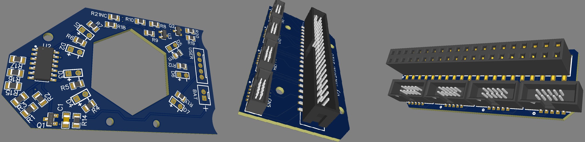
PCB/schematic projects will be published once they arrive and i verify they work as intended.
With any luck.
Edit: i forgot to transfer 100n capacitor from original schematic. Oh well. Looks like usual bypass cap, so slapping it on somewhere along voltage supply rails should work, right..?
Discussions
Become a Hackaday.io Member
Create an account to leave a comment. Already have an account? Log In.