 mkdxdx
I was not keen on to put here something small, so this update took an embarassingly long time to come up with, especially considering what came to fruition.
First of all - holy moles, the deck actually won the contest. I was hoping to get into some kind of notable category (painting this whole thing was tedious after all), sure, but this blew me away. Thanks Hackaday Team!
What I was working on was a way to route RPi GPIOs into primary module well, so it could function, as, well, a module well. So I could connect something there without disassembling the whole thing.
There was no way i could just grab a 2.54 20x2 and botch some 24AWG wires on it and run the whole bundle somewhere in the backplate until it surfaced in the module hatch. There are slots for that, yes, but it needs to be tidy to some extent and also there was no way to fit standard 2.54 headers onto a Pi - there was no headroom.
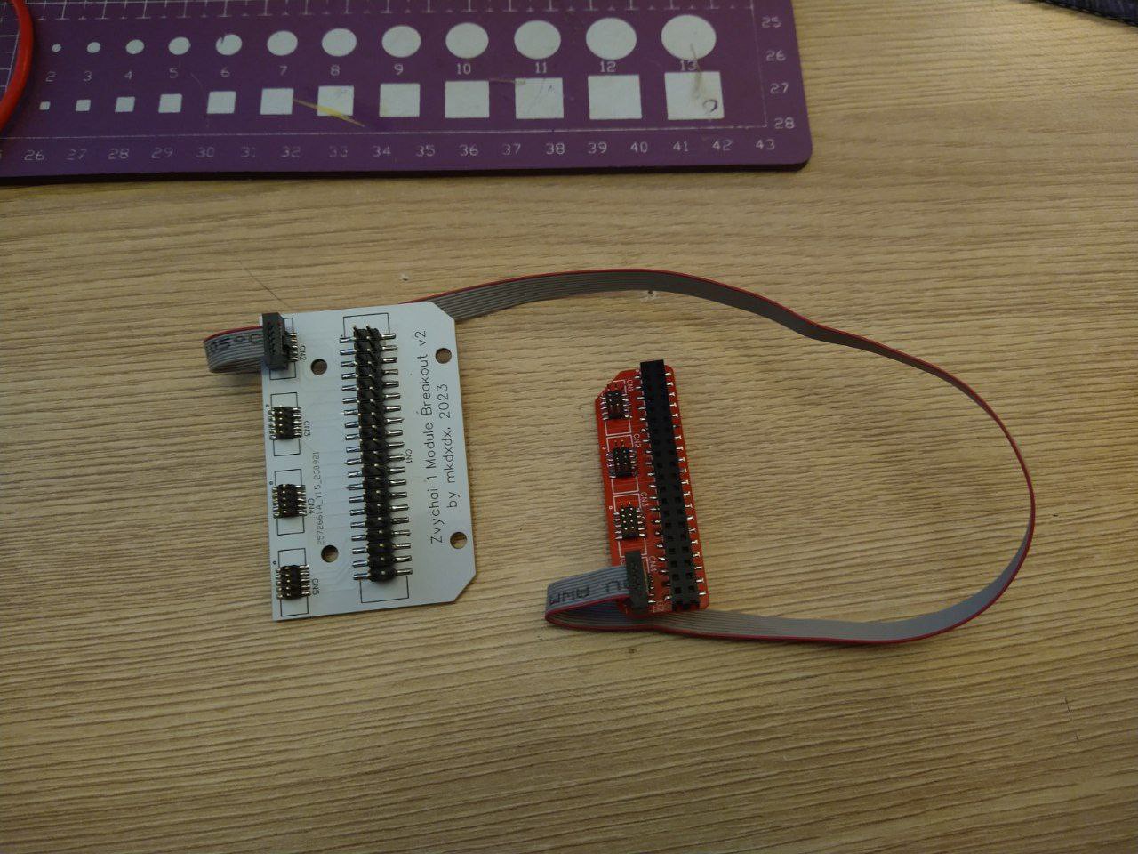
So i've decided to make two PCBs - one to convert GPIO header into something smaller (say, a flat cable) and then run that and convert it back into 2.54 format, more suitable for prototyping things.
First PCB order was botched - i did not check how they were connecting to eachother, so they were forming a mirrored GPIO layout. So i rerouted everything and sent everything back - that's almost two months before these arrived:


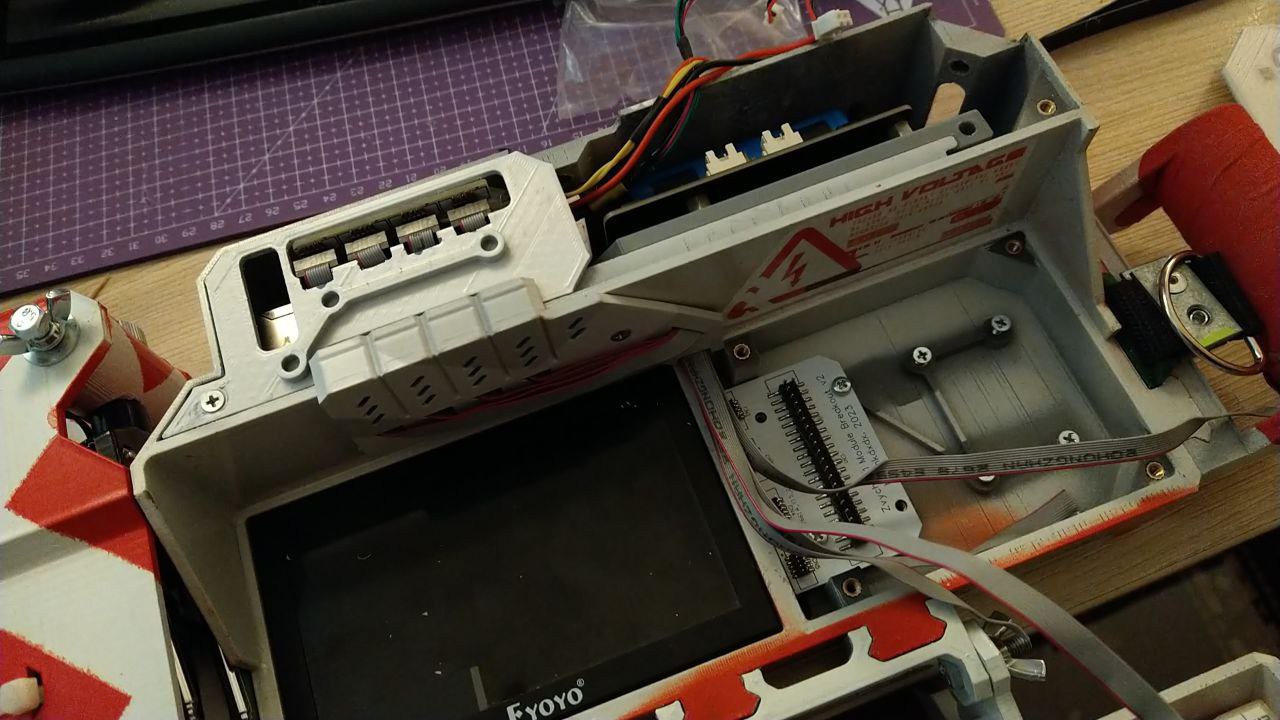
Looked tidy enough, but there was a problem. This bundle was lifting the back case cover and also it was permanent - you simply could not remove these cables without cutting those 1.27 IDC connectors. The permanency was the least of concerns, but that lifting business, that was a nono.

And it turned out - the top board was not fitting the primary cover (the one with a charging indication). And i was not in the mood to reprint and repaint it again. No, hell no. Next time, when chosing the CAD for PCB design - check thoroughly if it able to export into 3d cads with a proper format - EasyEDA can export either a good quality 3d model for referencing in case design - but the model will be wildly out of proportions, or it can export DXF - but that is 2D only and good luck deleting all the unnecessary shapes on that.
So, back to PCB design, another order, wait for another month of wait, all while redesigning the little left cover to fit the header. Another fitting job without actual reference hardware, another painting work, no red this time.
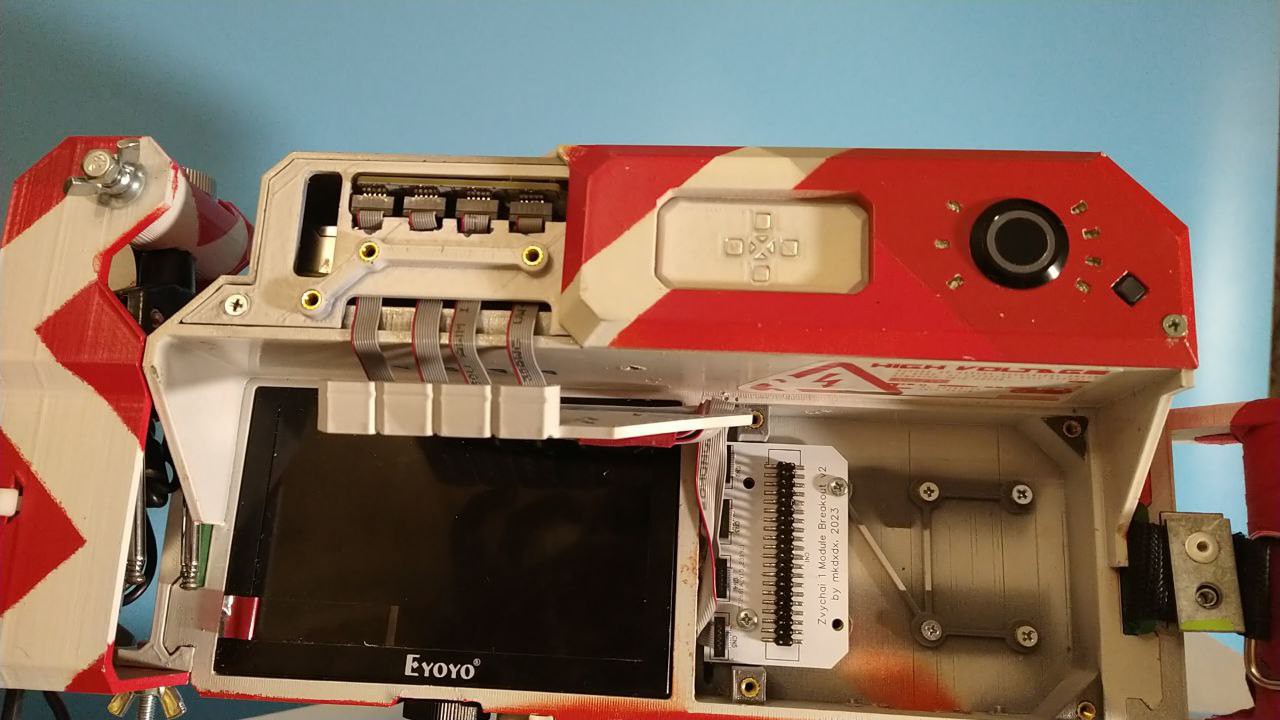
And finally it arrived - the new board is white, assembled and ready to be installed:

This time i've designed a little shroud that goes in front and supposed to contain all the flex cables in it.. But i miscalculated the thickness and could not make it any more thick either - it would not allow keyboard to close snuggly. So i've had to run everything semi-externally. Adds to the aesthetics i guess.
Oh and i've also had to cut the little cover to fit all the flex cables when they bend - i'm yet to update CAD files for that, so it may not be taken into account at the moment of STL uploading.


I was in such hurry to assemble everything, i skipped the part where i usually test everything with continuity tester. And so, naturally, the monster of short-circuits, the beast he is, just waits to bite your bum in the most unexpected and cruel way - i missed the short circuit on one of GPIO pairs and it resulted in, what is my best guess, a RPi PMIC going into thermal shutdown and not wanting to boot back again for some time. Almost had a heart attack at that point - some projects just hate me more than i hate them, i guess.
Fortunately, after cutting a connector and crimping another one, the short was gone.
Btw the layout on the breakout looks something like this - you look at the board to the left, and imagine your RPi board looks like the one to the right. Sort ot unconventional, but it works imo.

So RPi is back alive, and i needed some way to test if it truly works. Do something digital, but something on the cheap and quick. LoRa is out of reach for me (yet), so it needs to be simpler.
What do you do when you get the ability to connect digital stuff to your board?
That's right - you connect a strip of neopixels and vibe away.


And instead of a postscript - here is how charging indication board has evolved (from top to bottom). I've worked on it too while the whole business above allowed. A motivational reminder that when you persist - things, after all, move forward.

Discussions
Become a Hackaday.io Member
Create an account to leave a comment. Already have an account? Log In.