 Chris
ChrisThis is was going to be a way more in depth post about Rev. 3 updates but then my laptop died and nothing saved so I guess I will just type up a quick version for now.
There are a few main things that I need to change in Rev. 3. The biggest issue so far is that the battery charge never charges the battery fully. It only gets to 3.9 V. After some thinking and some tinkering I figured out the problem, and this was a great learning moment!
Battery Charging Woes
To handle the power switching between USB and battery, I threw a diode in front of the battery. That way VIN wouldn't go to the battery directly but when USB wasn't connected it would be the battery powering the system via the linear regulator. The problem?
What happens when the battery is no longer the path of least resistance.
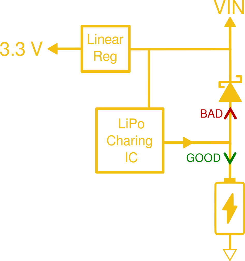
That's right, at a certain point in the charging the diode became the preferential current path meaning the battery never increased fully charged. After looking at the data sheet for the diode it worked out to a forward drop equivalent to about 2 Ohms. The fact that the impedance of the battery was high than 2 Ohms seemed strange to me but thinking about the crappy contacts and connectors it made sense.
I was able to confirm this theory but removing the diode and letting the battery charge up. Sure enough, that worked! I got the green light!

The battery charging solution
I poked around a little bit and realized that I just need to stop being lazy. The more correct way to handle this power off is with a P-FET and resistor.
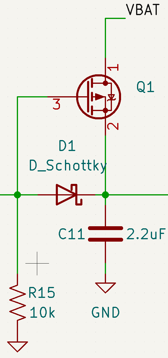
The idea here is that the P-FET acts like a Normally Closed switch. It will happily conduct until you hook up a VIN that pulls the gate higher than the source (P-FET are weird) and the P-FET opens, protecting the battery. I think this is something called an "ideal diode" configuration, or something like that.
Anyway! Figuring this out was honestly the easy part. The hard part was
1. Integrating ANOTHER chip and resistor onto this board.
2. Finding a small, cheap, and least crappy P-FET I could find.
In this case the "crappiness" is defined as the On Resistance of the FET. This parameter was especially important to me because when running on battery power you are running all the current through the FET. So if there is a super high on resistance that is basically just burning power.
Assuming an average current draw of 10 mA (just to make the math easy), using a diode in the configuration above gives a drop of about 2 Ohms. I managed to find a P-FET for cheaper than the diode with an on resistance of just 100 milliohms! Now we are talking!
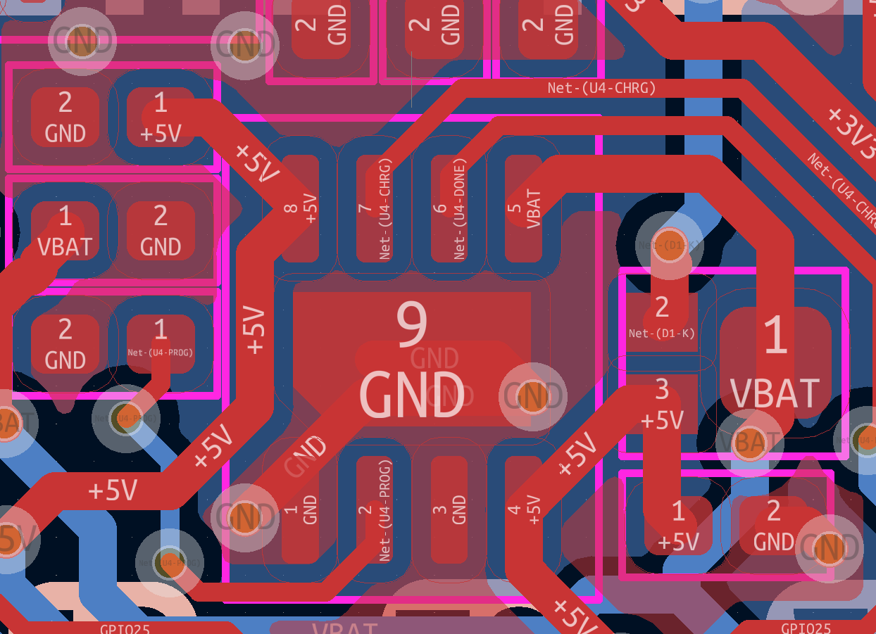
The next hardest part was just integrating it into the board! Thankfully I managed to do it without too much frustration. You can see the P-FET and extra resistor on the right hand side of the image below. This thing is TINY. Just 1.3mm by 1mm! What a time to be alive!
That's all for now. Slowly I am moving towards Rev. 3! Like I've mentioned before, I will be trying PCBWay for the next round of boards and I am super excited to get some more microscope pictures!
Discussions
Become a Hackaday.io Member
Create an account to leave a comment. Already have an account? Log In.