 Chris
ChrisI think I finally figured out my LiPo Charging woes! As a reminder, the LiPo IC would not fully charge the connected battery when a Schottky diode was present at the LiPo's output. This diode allows the CRAPi board to switch between USB and battery power with minimal fuss.
I figured adding a LiPo charger would make the CRAPi board way more useful, plus it would help fledgling dev board give the big boys a run for their money. Looking at you Adafruit and Pimoroni.
This was supposed to just be another IC and a few passives. Instead, I ended up dead-bugging a chip measuring 1.5mm x 1.5mm. With the hope of troubleshooting the circuit directly.
Yep. Check out the picture below. It really did feel like wire bonding!
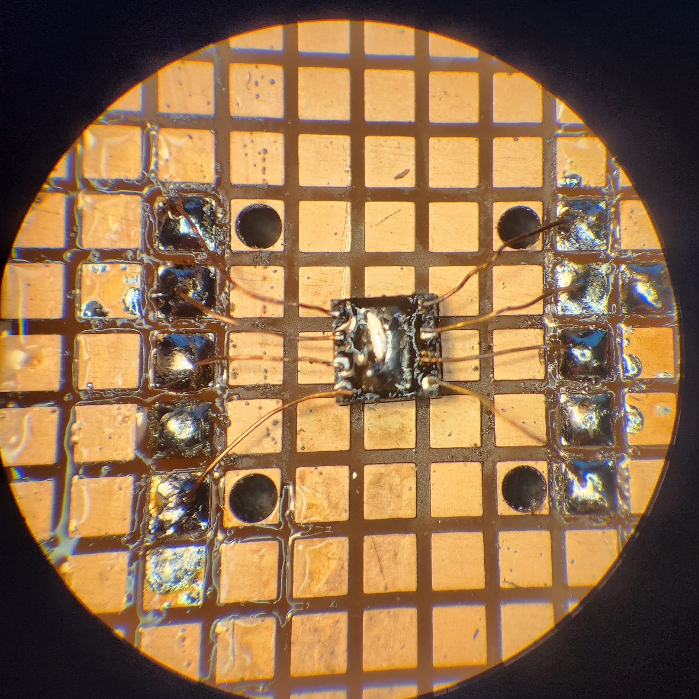
The copper wires are once again the strands from those cheap jumper cables. They are super thin and readily accessible. Unlike magnet wire, they don't have any insulation on them which I like. It means that I don't have to mess around burning varnish and the crust that comes with it. There isn't really much of a danger of shorts either, the wire is so thin that you can just route it around in midair and it stays put.
Here is a partial picture of the completed circuit. After the strong start with just the chip I was a little disappointed I couldn't do a better job on the rest of the circuit but I didn't have all night...
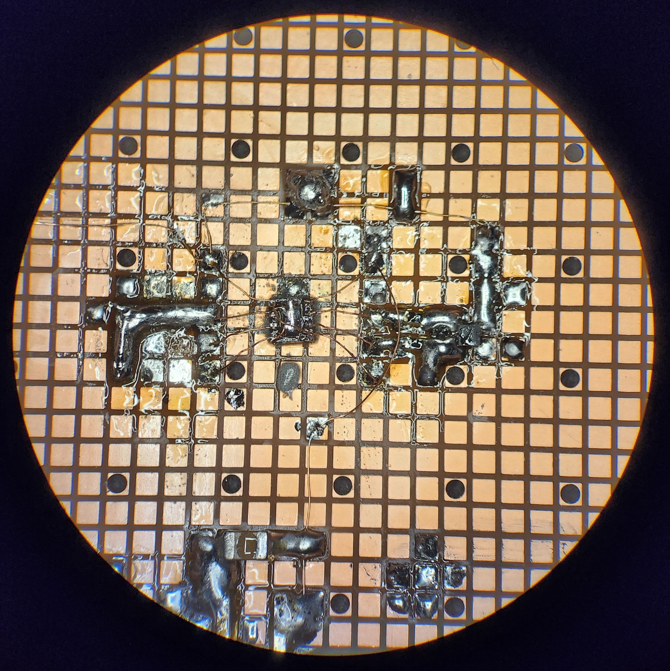
The fun part is that circuit did in fact work. I measured almost 100 mA flowing into the battery when I plugged it in! With the circuit working my next plan was to start messing around with diodes and dummy loads and what not and use this as my test bench.
After sleeping on it (and asking a smarter friend) I realized that would be a dumb idea. The diode really shouldn't have anything to do with it so there must be another issue.
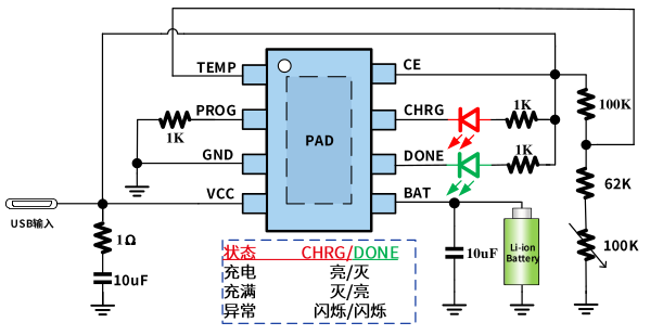
It occurred to me that I didn't actually put a 1 Ohm stabilizing resistor or a 10 uF capacitor on the input. I figured the traces on the board would be high enough resistance to replace the 1 Ohm and that the capacitance already on the 5V bus would be good enough that I could just slap down a 4.7 uF cap and call it a day.
Well after messing around with the capacitors close to the charging IC and observing some interesting and inconsistent behavior I realized that those components were probably included in the datasheet for a reason!
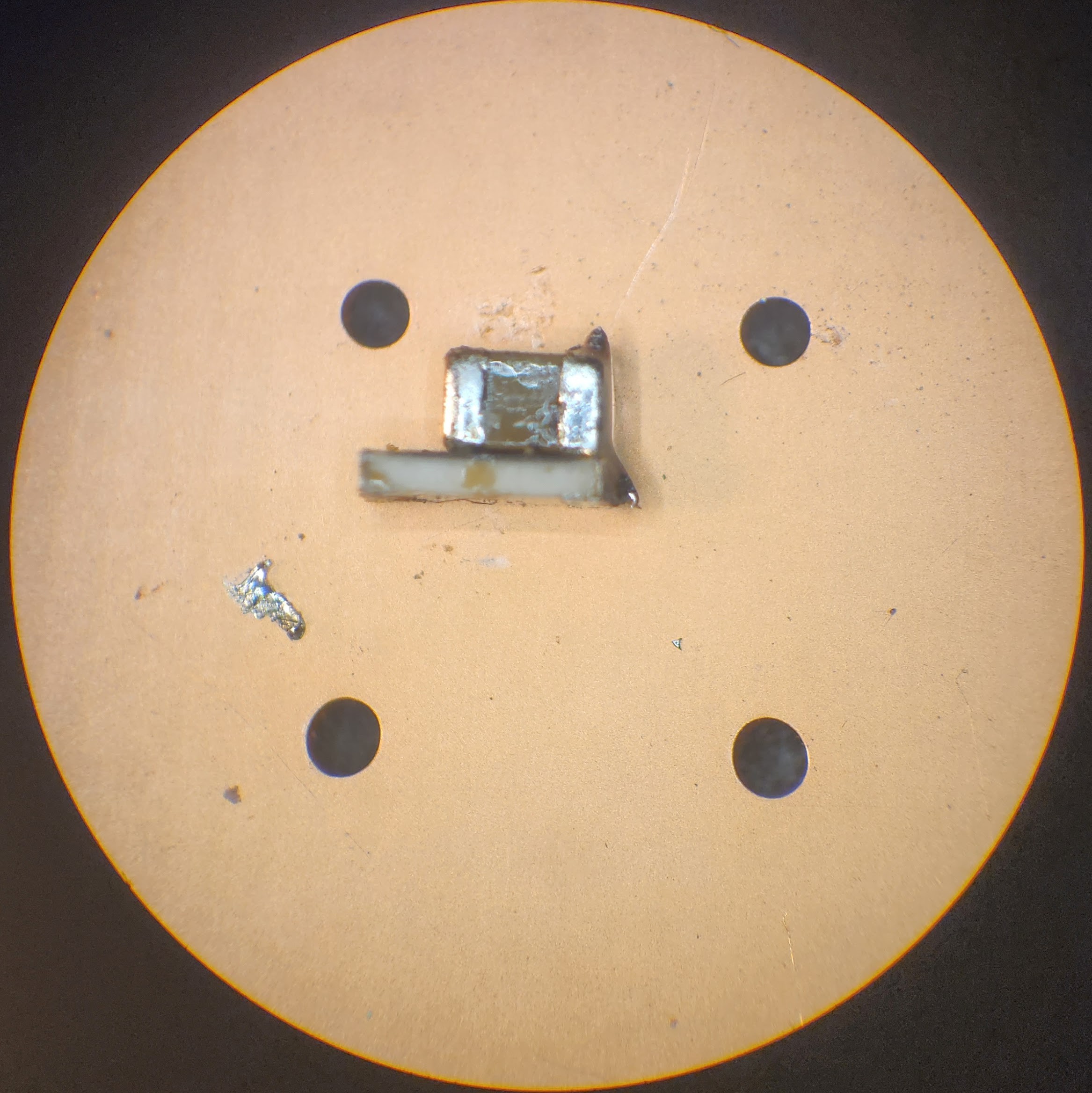
So instead of messing around with my crappy dead-bugged circuit I chose to just bodge the proper capacitors and resistor onto my test-board directly.
First I stacked a resistor and capacitor on top of each other and soldered their two ends together. The rest was just some time with some very very thin wire and the microscope.

SUCCESS!
This is probably my favorite bodge I have made to the CRAPi board so far just because it's sort of cool to look at. You can see that I added the recommended capacitance to the battery input as well as the recommended capacitance and resistance to the VCC of the charging IC.
Sure enough, after making this addition to the circuit the battery charged up all the way no problem, even with the diode. That leads me to think that there was just some weird instability or oscillation that was happen in the charging IC. This particular IC also has a trickle charge mode that attempts to revive dead batteries with < 1 mA charging currents if it detects an under-volted battery. I suspect that this has something to do with the problem as well, but without the time to stick the problematic circuit on a scope I won't know for sure. Oh well!
Sometimes you just have to move on.
Next steps.
This was pretty much the final technical issue with this version of the CRAPi board. I've already updated the Rev. 3 PCB to include more capacitance and the (apparently) very important stabilizing resistor. I am nearly done updating the silkscreen to clearer and more descriptive of the "hidden features" of the CRAPi board.
I've also gotten rid of the (apparently unproblematic) Schottkey diode to handle the power switching. I replaced it with a nice little P-FET. The Schottkey diode was like powering the CRAPi board through a 2 Ohm resistor so it was just burning power. The P-FET has an on-resistance of only 100 milliohms. Is that improvement worth adding another chip to the BOM? I'm not sure! But it does feel better.
After I update the ProtoGrid Rev. 3 will be ready!
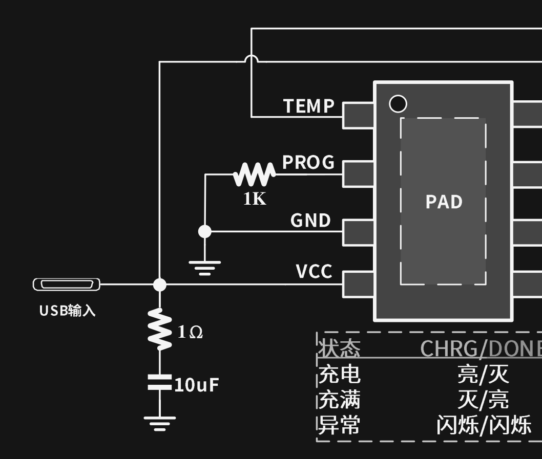
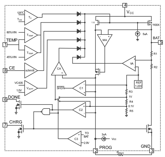
EDIT: Including block diagram and example circuit for for further discussion on charging woes.
Discussions
Become a Hackaday.io Member
Create an account to leave a comment. Already have an account? Log In.
I'm looking at the diagram and it looks like they are utilizing the schottky diode's reverse leakage current which increases with temperature. When it gets hot enough, then enough current will leak to trigger the temperature pin. I could be wrong but I'm pretty sure you've taken out the overheating protection.
Are you sure? yes | no
Unfortunately, the Schottky was my addition and not in the data sheet, but still an interesting thought. You are correct though, I have taken out over heating protection. Most of "hobby" cells don't include an integrated thermistors.
Looks like I may have been a victim of improperly de-rated capacitors...
Are you sure? yes | no
Power chips have always seemed like an analog black box and not following the example circuit is just asking for trouble. I'm glad you found the problem and I hope learned something from this. Also, yeah, that's manual wire bonding scale soldering.
Are you sure? yes | no
I found the solution but I didn't find the problem. Which sort of sucks. I updated the log to include the block diagram for the LiPo charger and the full example circuit. Maybe the Schottky across the BAT and VCC pins caused some sort of weird oscillation that wasn't damped out...
I'm open to theories at this point.
Are you sure? yes | no
It looks like without the resistor, VCC was freely flowing into GND. It kind seems like all the power from the USB port was just flowing into that one capacitor.
Are you sure? yes | no