 trax
traxThis device is connected to mains power line therefore it requires a lot of respect. If you are not sure in what you are doing, you better leave the installation part to the experienced electrician. Even though this device operates on 5V DC, when connected to mains voltage it can still kill you if you touch any part of it!
You can safely assemble it on your bench, but once it is connected to the mains, DO NOT TOUCH IT!
Introduction
I recently decided to publish this project on my webpage so I decided to send it to 1kB Challenge here as well. The firmware has been optimized to fit within specs of the challenge and source code is written in Microchip Assembly. You can download MPLAB from www.microchip.com and assemble a version with your own modifications! There is much room to spare in PIC (whole additional 1kB!).
How this device works is pretty cool, it powers itself from the mains through the load (usually a light bulb but it can also be a resistive heating element). The way it turns the load ON is by short-circuiting its own power supply! You can control it with your own TV remote controller - all you need is 4 spare buttons (usually those used for Teletext so that they don't interfere with normal TV usage). If you can't spare 4 buttons you can teach the device just 2 buttons, but in this case you either loose the dimming functionality - you can only turn the light on and off, or you loose the OFF button so you would need to dim-down to level 0 in order to turn the lights off. It recognizes two IR protocols: NEC and RC5 (mostly used in the world).
How it works?
Transformerless power supply
The device is powered from the mains voltage using capacitive power supply. You should read all about it on this link: http://www.designercircuits.com/DesignNote1a.pdf and also this link: http://ww1.microchip.com/downloads/en/AppNotes/00954A.pdf
Stand-By (lights Off)
The
device powers itself from the mains voltage, through the resistive load
(light bulb). It consumes very little power (< 5mA) so the light
bulb does not glow during stand-by. The main consumer is the TSOP IR
receiver, but you can also use low-power TSOPs such as TSOP38238 if you want to bring this down to under 1mA. In this state, PIC microcontroller is waiting for IR signal from TSOP or a press from the wall switch.
Please bear in mind that wall switch must no longer be a classical on/off switch - it must be replaced with a push-button switch that closes the contacts only while you keep pressing it.
In this state the triac is not fired and nothing special happens.
On-State (lights ON or Dimmed)
If a wall switch is pressed or appropriate IR signal is received from the remote, the light bulb will turn ON. Turning the light bulb ON is accomplished by firing the Triac when mains voltage cross the zero point. This is detected with the zero-crossing detector formed with R3 and C6. If we trigger the Triac right after the "zero" has been detected it will turn the lights ON at full intensity. If we delay the Triac firing by some time we can effectively perform dimming as the voltage that appears at the output is smaller than the supply voltage. You can read the app note from ST here: http://www.mouser.com/catalog/specsheets/stevalill004v1.pdf (serial-dimmer such as this one can be found starting from page 16). This app note also contains calculations for the transformerless power supply - so check it out as well!
If we look at the circuit schematics - the power supply part, we can see that when Triac starts conducting it short-circuits our transformerless power supply. At this point entire circuit is powered from capacitor C3. It should be large enough to keep enough power for TSOP (~5mA), PIC (< 1mA) and MOC3023 (~5mA but only for a few microseconds) so don't be shy to use larger-valued capacitor here, such as 220uF/330uF/470uF. If we keep the light turned ON at full brightness it will eventually discharge the C3 completely and restart the PIC microcontroller....
Read more »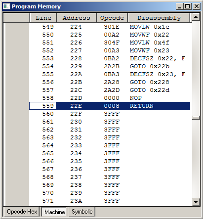


 DominicM
 G. Rosa
 Alpenglow Industries
 Just4Fun
Hi,
In my opinion in the schematic has an problem. The optocoupler 1 pin is anod. therefore is it can not be GND
?