 Bharbour
Creating a continuous weld around a tube or other round object with common shop equipment, requires a way to rotate the work piece while the weld is being done. Welding of gas and vacuum systems require a continuous weld completely around the work piece for leak prevention. Professional pipe and tube welding shops use what is called an orbital welding machine that rotates the arc around the weld, but these are expensive, specialized machines. A simple tool to rotate the work piece with a variable speed motor drive is a reasonable thing to make for a home shop.
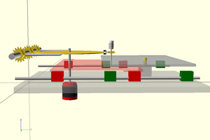
These two positioners can be set up face to face, with the work piece horizontal, as you would want for welding tube or pipe. The bore on the positioners can work with an object up to 2 1/2" (6.3cm) in diameter passing through the clamps.

Using just the powered positioner, a table can be bolted to the face of the clamp on the positioner and the positioner laid on it's back to work with small objects sitting on top.

A step motor is used to drive the positioner because it can run very slowly and is easily controlled. Scavenging around at the local surplus yard yielded a usable motor and driver board. A power supply and a source of step pulses is all that was needed to complete the motion control part of the project. A 555 with a potentiometer to vary the step rate supplies the step pulses. A foot switch on top of the enclosure lets the weldor start and stop the motion.

The 5 pin XLR connector provides the connection between the motor and the control box.
Most of the welding that I do is Tungsten Inert Gas (TIG) and it uses high voltage, high frequency pulses to start the arc and in the case of aluminum welding, the high frequency runs throughout the weld process. Keeping the high frequency energy out of the step motor control is necessary. The weld current is isolated from the step motor system by mounting

the motor on a sheet of fiberglass. Plastic sprockets isolate the chain from the motor shaft. Wiring between the motor and the control box is run through a shielded cable to minimize coupling into the wire.
The pillow block roller bearings that support the work clamps were the only piece of the project that was bought new for the project. The work clamps were turned from a piece of 3 1/2" (8.9cm) diameter, 1/2" (12.7mm) wall tube left over from another project. It was necessary to turn the diameter of the tube down to 3" (7.6cm) to fit through the bore on the bearings. The holes for the radial clamp screws and the table mounting screws were drilled and tapped. A sprocket was bored to fit the on the work clamp and welded to the back of the work clamp. A second plastic sprocket mounted on an eccentric bolt serves as a chain tensioner.

Roller bearings do not survive passing welding current through them. The spring loaded bar with the red cable on it in the picture above, provide a path for the welding current from the work clamp to the frame of the positioner. The motor driven positioner has a similar connection to the work clamp but the other end of the cable goes to a bolt that is electrically isolated from the frame of the positioner. The aluminum wiper arm is also mounted to the fiberglass to keep it isolated. In normal use, the manual positioner is not used as the weld current path.
A box for the motor driver electronics was made from left over diamond plate aluminum. Frames for the positioners were welded up from 1" (2.5cm) square steel tube.
 Philip Ashmore
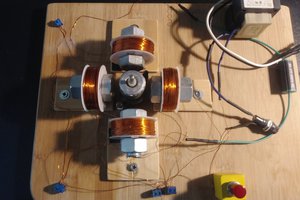
 G. Rosa
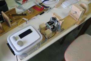
 shlonkin
 Quinn
Quinn