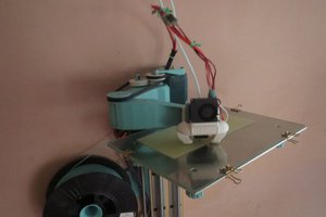
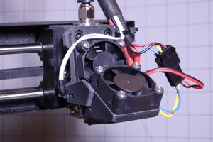
The final version is much more polished. Photos of it along with more details are below!
Note* I started this project with an already modified K40. We cut down the exhaust intake to give us more room in the Y axis. If you want to use this design then you will likely need to do the same, or remove the part of the exhaust where it is closest to the bed of a stock K40. If you don't, you should still be able to make this work, however you will have to trim the aluminum to different sizes, and get a different belt length.
Parts
Hardware
(Note that these are the exact parts that I used to model this, so if you use parts with slightly different dimensions, then you will need to modify the 3d models)
1/2" X 1/16" thick aluminum angle (8ft long - Menards, Home Depot, etc)
These are the sizes that each piece will need to be cut to.
- 3 X 300mm long (X axis)
- 2 X 120mm long (X axis)
- 4 X 160mm long (Y axis) These may need to be different if your K40 wasn't modified like ours
- 4 X 100mm long (Z axis)
8mm linear rod (At least 450mm in length)
(I used chrome plated rod, but drill rod will work just as well for this application. You won't use the Z axis as much as you would in a normal cnc application)
- 4 X 110mm long (You can get some cheap chrome plated stuff Here )
M8 1.25 Threaded rod (At least 500mm in length)
- 3 X 110mm long (This is basically what I used for Threaded Rod X 2)
- 1 X 140mm long (this is if you want the manual override knob)
M3 Threaded rod
(This was kind of a last minute addition. I used this for the belt tensioning mechanism, but there are better ways of doing it)
- At least 300mm in length
8mm Bushings
- 4 x 8mm i.d X 10mm o.d X 10mm long bushings. (I used these exact 8mm bushings. If you use any others than you will need to adjust the 3d models accordingly)
GT2 Pulleys
- 4 X 20 tooth 8mm Bore (I bought them Here )
- 1 X 20 tooth 5mm Bore (I had one lying around but it can also be bought Here )
608 Bearings
- 8 X 608zz ball bearings (You can get a pack of 10 Here )
C clips
- 4 x 7mm C clips (These will attach to the bottom of the threaded rods)
Heat Inserts
(these are used to add threads to all the 3d printed parts. I just used a soldering iron to press fit them)
- Aprox. 40 X M3 5X5mm heat inserts (I bought mine Here )
- At least 2 X M5 heat inserts (not sure of the exact diameter used, but the wholes are 8.2mm in diameter, so your insert must have a slightly larger diameter than that)
Screws
- 2 X M5 x 28mm (26 - 28mm should be long enough. I had to cut some to length)
- At least 30 X M3 x 10mm (I would just buy some in bulk, but 10mm should be long enough for everything. If you plan on drilling and tapping the aluminum angle though, then you will need more than 30)
- 4 X M8 1.25 Nuts
GT2 Belt
(This is the one critical thing where the exact length does matter. We are using a closed loop belt, so I had to order an exact size. Getting one too large will increase the amount of slack, and getting one too small will make it useless) Remember that I started this with a modified K40, so you may need a different belt length depending on your K40!
- 1 X 6mm wide 1210mm long GT2 closed loop belt (This is the only source that I could find)
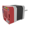
Nema 17 motor
- 1 X 34mm long Nema 17 motor. (The length of the body is somewhat critical for clearance issues, so I wouldn't get one any longer than 34mm) This one will work.
Endstop Switches
- 2 X SPDT switches (I used these but I would not recommend them. Basically any similar micro switch will work)
Aluminum Bed
- 1 x 350mm X 250mm bed. (I used this, but it is almost overkill for this application. Pretty much any expanded aluminum or laser bed material will work)
3d Printed Parts
All of the STL files can be found Here
I have also provided the STEP files in case you need to modify the 3d models at all.
I printed all the parts in PETG with 3 shells and a 20% infill.
You will need to print
- 1 x Knob.stl (for manual adjustment of the Z axis)
- 2 x Bed Mount.stl (This is what the aluminum bed attaches to)
- 2 x Bed Mount Mirrored.stl
- 2 x Bed clamp.stl (this is what clamps the aluminum...

 dekutree64
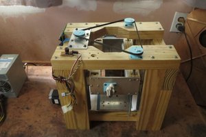
 U.S. Water Rockets
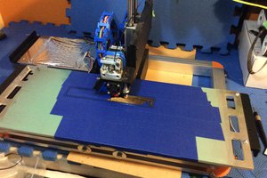
 ken.do
can you make me one please. Whats your cost? smity82au@yahoo.com