 mircemk
Li-Fi is a light communication system that is capable of transmitting data at high speeds over the visible light, ultraviolet, and infrared spectrums. The term was first introduced by Harald Haas in 2011. The Li-Fi system consists of normal LED light bulbs and modulating circuits.

LED bulbs are semiconductor devices, which means the current, and therefore the illumination can be modulated at extremely high speeds which can be detected by the photo-detector.
Using this technique allows for high-speed information can be transmitted from an LED light bulb. So, the same light energy used for illumination may also be used for communication.

In this experiment I will describe you a way where the light from 10W Power LED diode is used for this purpose as a medium of transmission. To reduce the losses at the lowest level, we direct light from the source through a plane convex lens, so if the light source is positioned exactly at the focal point, the light rays on the exit will extend almost parallel and directly hit the receiver (solar cell) with the least loss.

If you want to make a PCB for your electronic project, PCBway is a great choice for you. PCBway is one of the most experienced PCB manufacturing company in China in field of PCB prototype and fabrication. They provide completed PCB assembly service with worldwide free shipping , and ISO9001 quality control system. Also, on their site there is an online gerber viewer where you can upload your gerber and drill files to render your board.

In this way, the distance at which transmission can be carried out is drastically increased, and at the same time, due to the strong intensity of light that reaches the receiver, the influence of the ambient light has an insignificant effect.
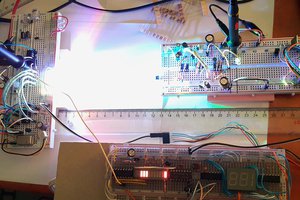
As I mentioned earlier, the experiment is very simple to replicate and consists of several parts:
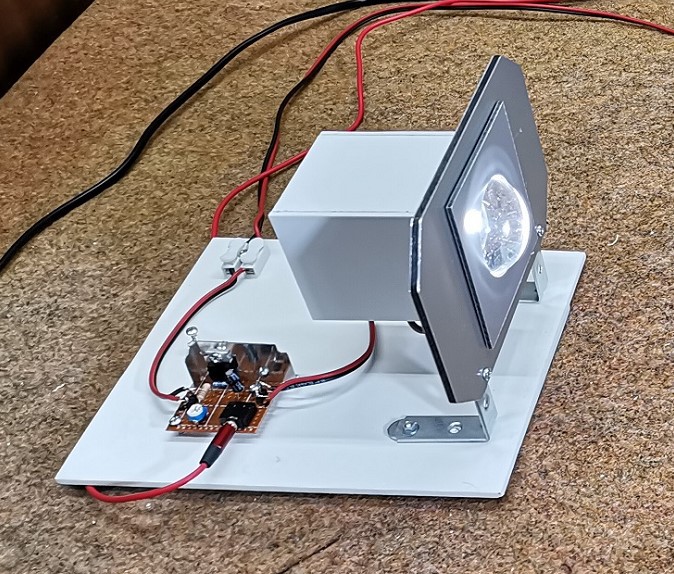
- The transmitter, which consists of an LED that is mounted on a suitable heatsink and can be moved in this channel to position it exactly on the focal point.
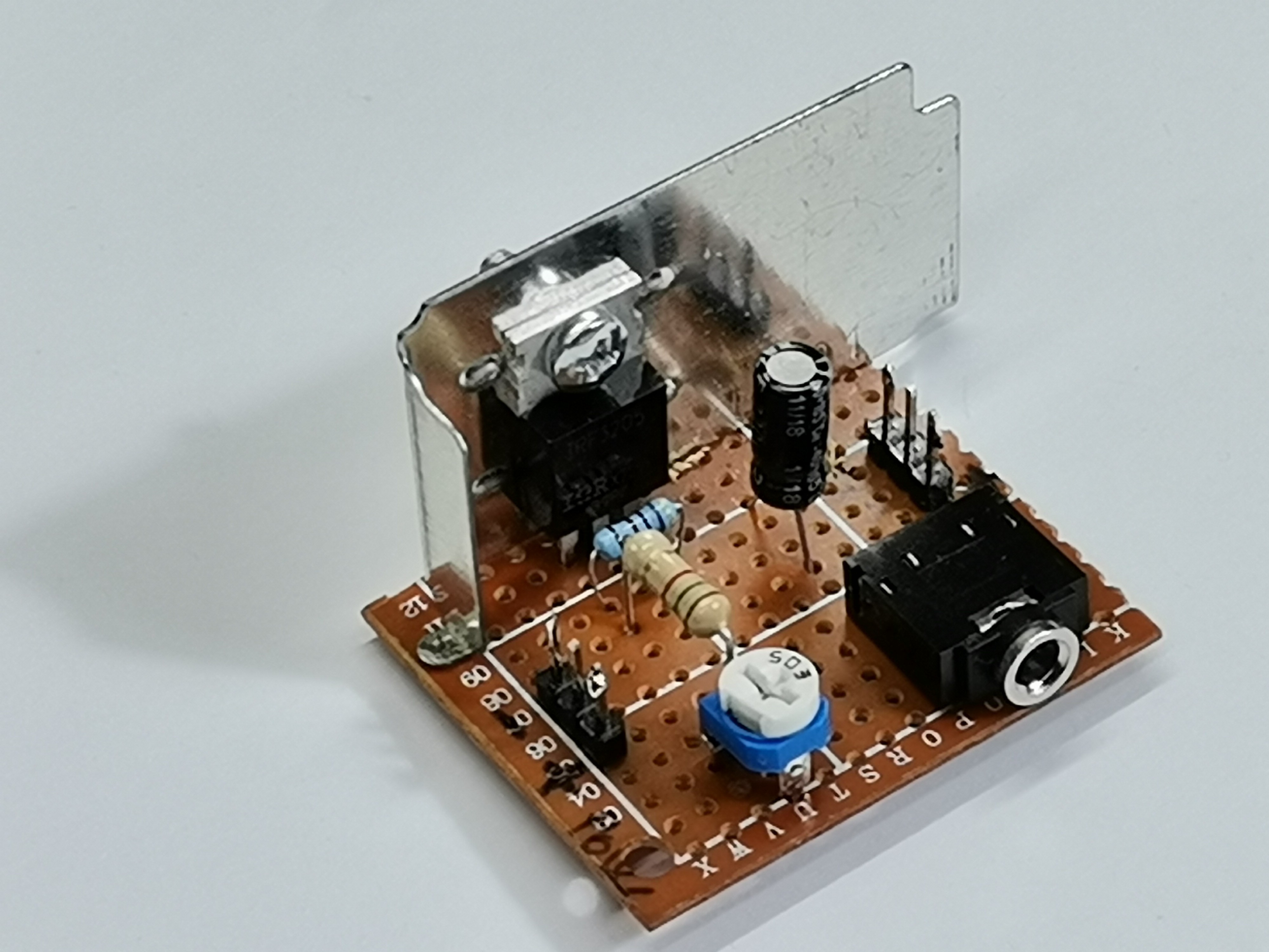

- And a DC voltage source that powers the transmitter.
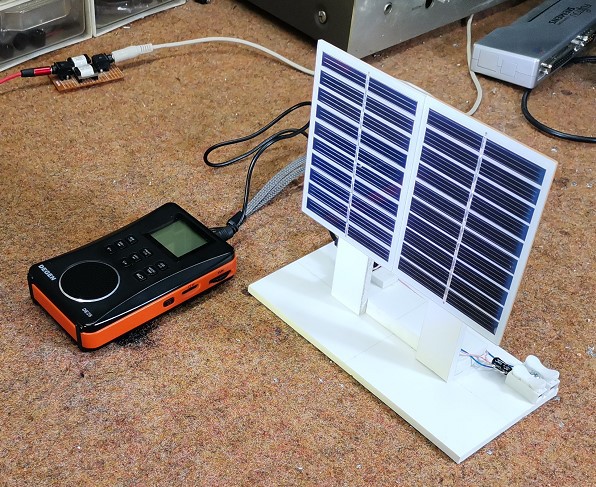
- The receiver is actually a solar cell, in my case two elements that generate 5 volts each connected in series, but this is not critical and any panel we have at hand can be used. The signal from the solar panel is fed to the Aux input of this small radio receiver through a 10 microfarad capacitor, whose function is to not pass the DC component of the signal. Otherwise, this radio in this case has the function of an audio amplifier.
Now let's see how the device works in reality:
First we turn on the transmitter and focus the output beam. An audio signal is brought to the input of the modulator, in my case from the sound card of the Personal Computer. On the side of the receiver, we turn on the radio, then we select the Aux input. The signal from the transmitter is emitted on the receiver. If we block the light beam, the transfer is interrupted.
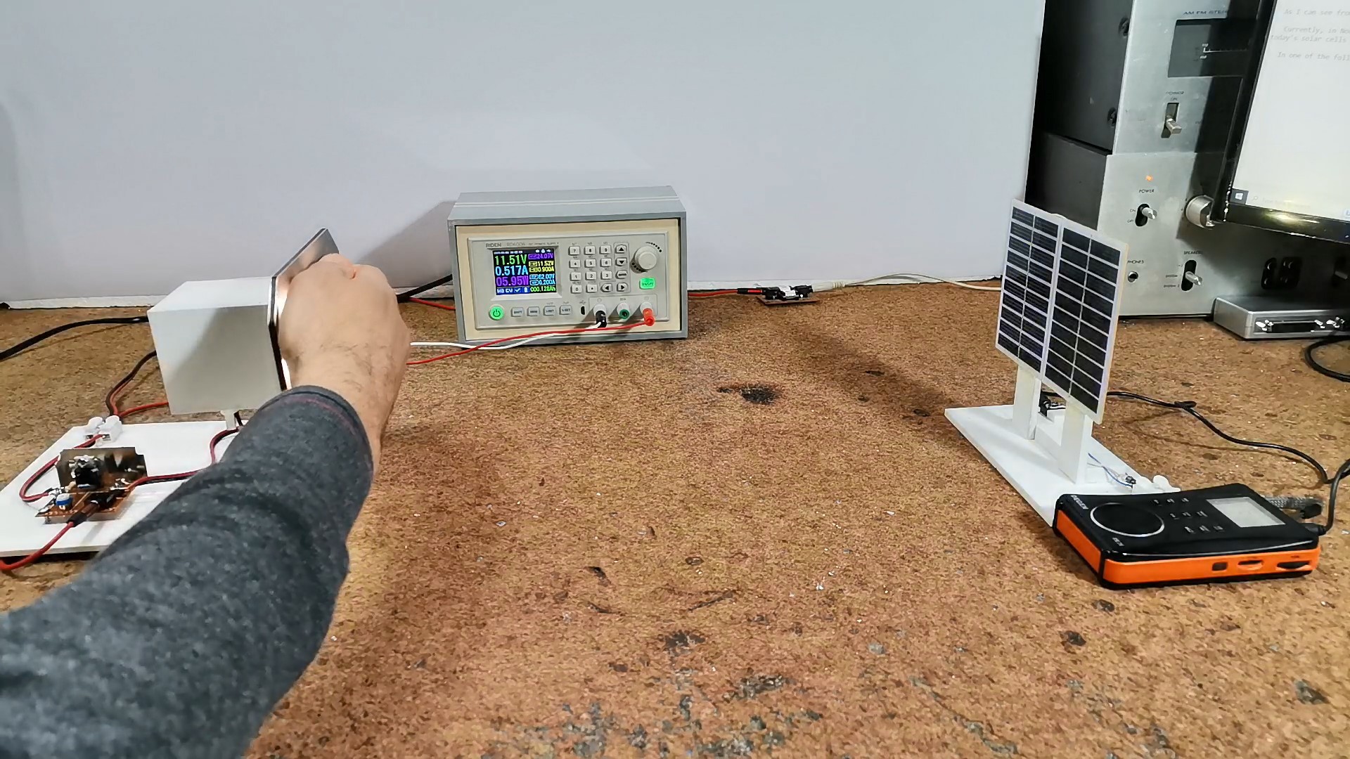
The distance between the transmitter and the receiver can be increased up to a certain limit that depends on several parameters. In our case it is a maximum of 5 to 6 meters with acceptable signal attenuation.
Next I will present you a practical example of transmitting an Audio signal through a room lighting source. We connect the lighting through a modulator, and a small solar panel is connected to the receiver.

Now if I feed a music signal to the input of the modulator, that same signal will be output to the radio. Many different signals can be transmitted in the same way, such as the Internet, which is the most used service today.
And finally, a short conclusion: First the positive aspects
- As we could see and hear, the transfer is done...
 Jovan
Jovan
 Rainer Glaschick
 Arkadi