 agp.cooper
Simulating the BJT Mixer
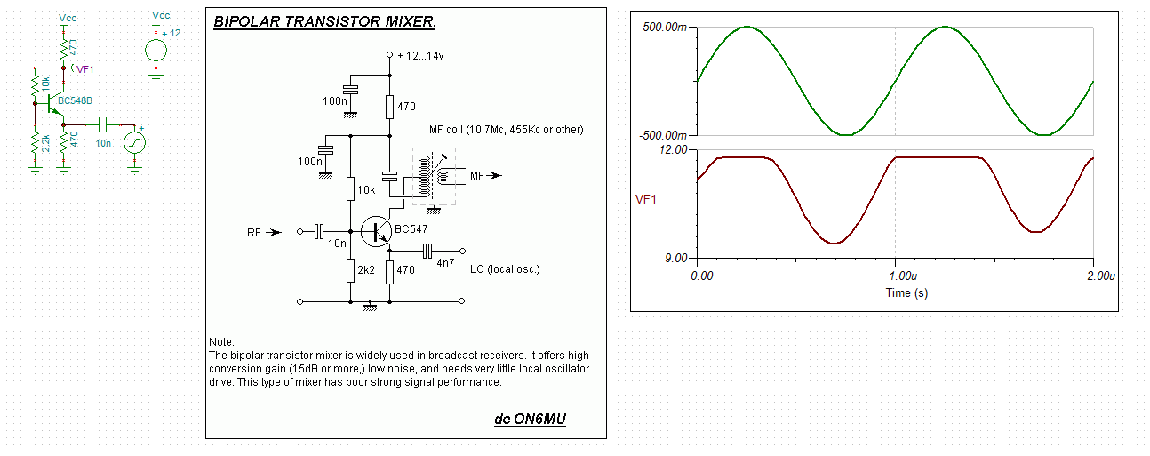
After searching the Internet I did find a few circuits with component values and local oscillator power requirements that allowed me to digitise a schematic in order to look at the simulation:
 (source: http://users.belgacom.net/hamradio/schemas/mixer1.gif)
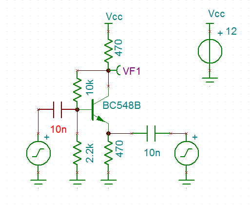
Here is my initial simulation:
Next lets mix in the signal:
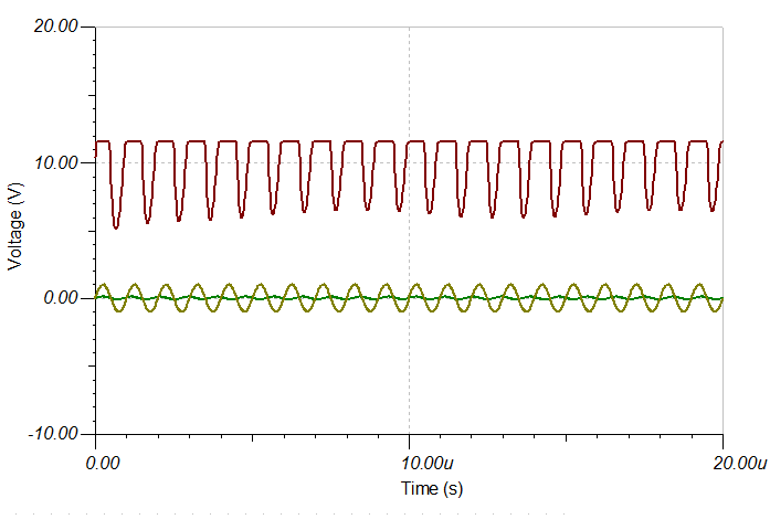
And what did I get:
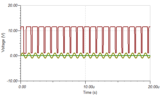
Now this is not right! Even with a uV signal?
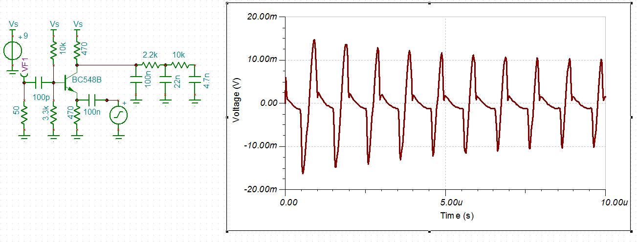
Okay reduce the coupling capacitor:
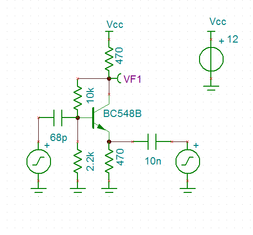
And now it works (all that is required is a low pass filter to extract the 100 kHz signal).:
Need to look at the range of couple capacitors values that work.
The above local oscillator (LO) is 1 MHz and 2v pp and the signal is 1.1 MHz and 200 mv pp. Getting a 50% duty (i.e. Class B operation) for the mixer requires adjustment of the LO amplitude or the bias resistors.
Conclusion
Well I am happy I now know how this mixer works. It is a switching mixer) configured as a Class B amplifier. It is now easy for me to design and to tweak.
Recovering Audio
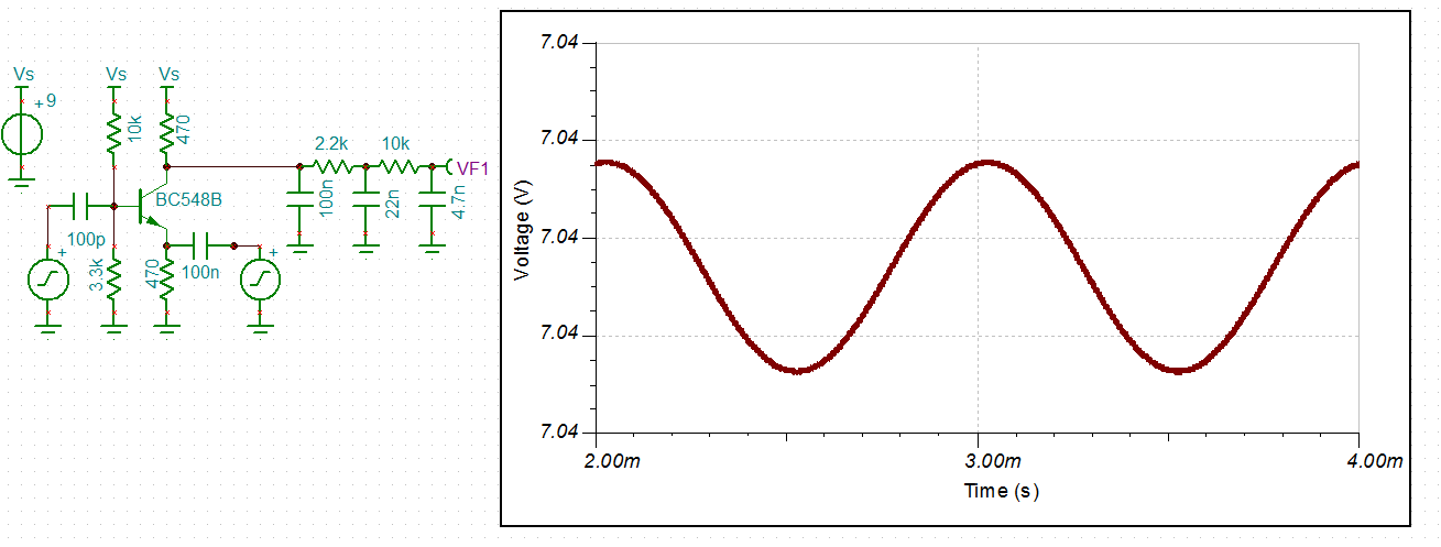
The modulated RF is 2 mv pp and the recovered audio is 1 mv pp. The line thickness is due to left over RF. Pretty happy with that.
Port Isolation
How much is the LO isolated from the input? Practically nothing gets through:
That is 20 mv pp from a LO of 1.4 v pp.
Regards AlanX
Discussions
Become a Hackaday.io Member
Create an account to leave a comment. Already have an account? Log In.
Okay
Yes a tuned circuit would be found in most practical designs but I am trying to understand how the circuit works and RC networks simulate without issue. The same cannot be said for LC circuits. The LC (tank) does not or should not influence the mixing by the transistor. Mixing as you would know is a non-linear transfer process (by the active device). So I don't need the tank to model mixing.
I am not sure what is meant by the second comment. The words "should" or "should not" may be missing from the sentence? And which 470R resistor (the collector or the emitter). I assume you are talking about the collector resistor and the 100n bypass?
In this case, the RC network is an audio band pass. The low pass corner of the 470R and 100n LP is approximately 33kHz. So its okay for my simulation (as the aduio signal was 1kHz).
---
Okay, it is a product detector rather than a IF mixer. Still the project was about understanding how the transistor mixer works, rather than the 455kHz IF mixer.
What was surprising for me in the investigation was that the circuit was working in Class B. I initially assumed it would have been operating in Class A.
Regards AlanX
Are you sure? yes | no
Hi Alan, I have a question: why you simulate the output with just a resistor, you have transformer with a resonant circuit at the output, this resonant circuit will attenuate all the armomics giving you a more cleanest waveform....
Also the 470 ohms resistor have a bypass capacitor, the medium frecuency (MF or the beat freceuncy ~ 455khz) will never reach this resistor
Are you sure? yes | no