 CentyLab
The 2nd iteration covers all the mistakes made in the previous one:
- 5.1k Ohm termination on CC1 and CC2 to GND
- QuadSPI flash
- Crystal oscillator with 50Ohm ESR
- 1K series resistor to limit crystal oscillator drive
- USB trace set to 90Ohm differential impedance
Additional upgrade:
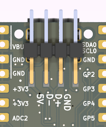
- Breakout USB header to have extra D+/D- and 5V input
- Blocking diode between 5V input and VBUS
- Easier to press buttons
Design challenges
The initial design has USB D+/D- connected only to the USB-C. If using the USB-C only, the user has two options,
- Connect to PC: programming and serial debugging, no USB PD.
- Connect to USB brick: running existing code without the ability to flash or serial debug the code.
All of this can be solved if you have an external flasher and debugger tool like Pico Probe using the SWD pins. Pico Probe works well with PlatformIO to compile and flash C++ code, but for MicroPython code using Throny, check out this method of packing your files into .uf2 and flash using PicoProbe. It is not as easy as just plug in your USB cable and flash it!
What if we add extra header pins for the USB cable and a switch to select where the D+/D- comes from?
The RP2040 has USB 2.0 hardware that is running at full speed. This means the fastest driver rise time is 4ns. FR4 propagation time is 6 inches/ns. We have a signal propagation distance of 24 inches over the 4ns rise time. If we are conservative and take 10% of the critical length, we have 2.4 inches of critical length that we can lose on impedance control. -> We have no problem losing impedance control over one 0 Ohm jumper 0402 resistor and one via.
Now when adding the extra header, if not connected, we have a permanent trace stud on the D+/D- line. This stub can impact the signal by creating a reflection when the signal travels to the end of the stud and bounces back. Following this rule of thumb to calculate the max length of the stud and USB 2.0 Fullspeed @ 12Mbps, we have:
maxStudLength (cm) = 0.75 / BitRate(Gbps) = 0.75 / 0.012(Gbps) = 62cm.
62cm seems to be too long! However, if that is the case, we can have a permanent header sticking out at 1.4cm + (0.5cm for traces) without much of a reflection problem.
Discussions
Become a Hackaday.io Member
Create an account to leave a comment. Already have an account? Log In.