MatNieuw
Clock generator
Choose R1 so that the relay reliable engages.
R2 is ideally such, that the parallel resistance of the relay coil and R2 equal R1. In the example, 1500 parallel with 700 gives 477 ohm.
R2 determines duty cycle (within limits), I got 75+85 ms per cycle. Different relays will need different component values.
C1 determines frequency, in my test I selected for 6 Hz. Lower C1 values give higher frequencies, but the relay switch time becomes a larger part of the total cycle time.
A third set of contacts on the relay would enable an inverse clock too, possible with some dead time between the two due to relay switching time.
With another relay one could at selected times add Cs parallel, to lower frequency, when a slower clock is desired e.g. for a slower circuit. Such a C should always be connected to GND at the minus side, and permanently fed at the plus side via a high resistance value (say, 1 M Ohm) from a voltage equal to the lowest voltage on the relay, to prevent wrong pulses when it is switched
parallel to the existing C.
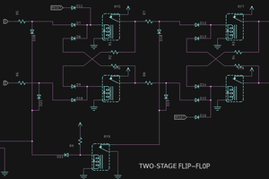
Latch:
Choose R1 and R2 so that the relays reliably holds. In my tests, with 24V/700ohm relays, 1k2 ohm gave the minimum hold voltage according to the datasheet, but my relays held fine with 1k8 too. It saves energy too, when in hold mode.
If K1 is activated, input data (here D0 and D1) is connected to the associated relay. If the input is VDC, a storage relays will be activated if it was not, otherwise it stays activated. Once activated, it stays activated if K1 is de-activated because of the resistor.
If the input is GND, and the K1 is activated, a storage relay will get 0 volts across it and is de-activated. During the storage relay release time there will be a current from VDC to GND, which is higher that the normal relay current, but it lasts only a short time (5-20 ms or so).
This circuit can be expanded to as many bits as required. The write relay (K1) can be a multi pole single throw version. This DPDT here was chosen for commonality with the other relays.
Propagation time input-to-output: two relay switch "make" times worst case.
 Ted Yapo
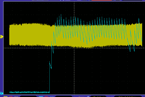
 Yann Guidon / YGDES