 Denys Zaikin
History
- Two modules had been bought and both of them were damaged in trying to power up without limiting the resistor.
- Then RF2126s were replaced.
- Power supply and biassing were performed correctly and the quiescent current was stable.
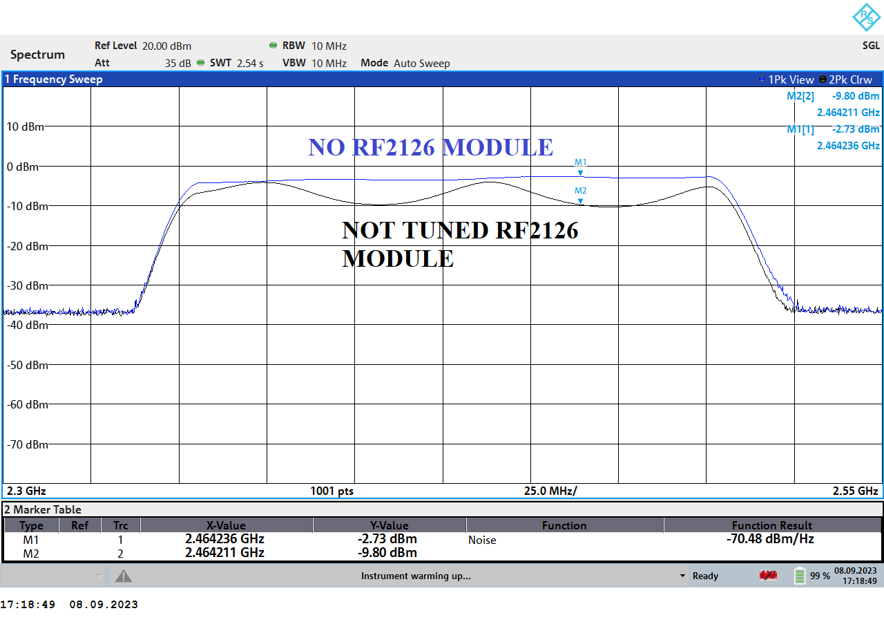
- But the power gain was very bad, with no amplification at all at 2.45GHz.
.
Power supply notes
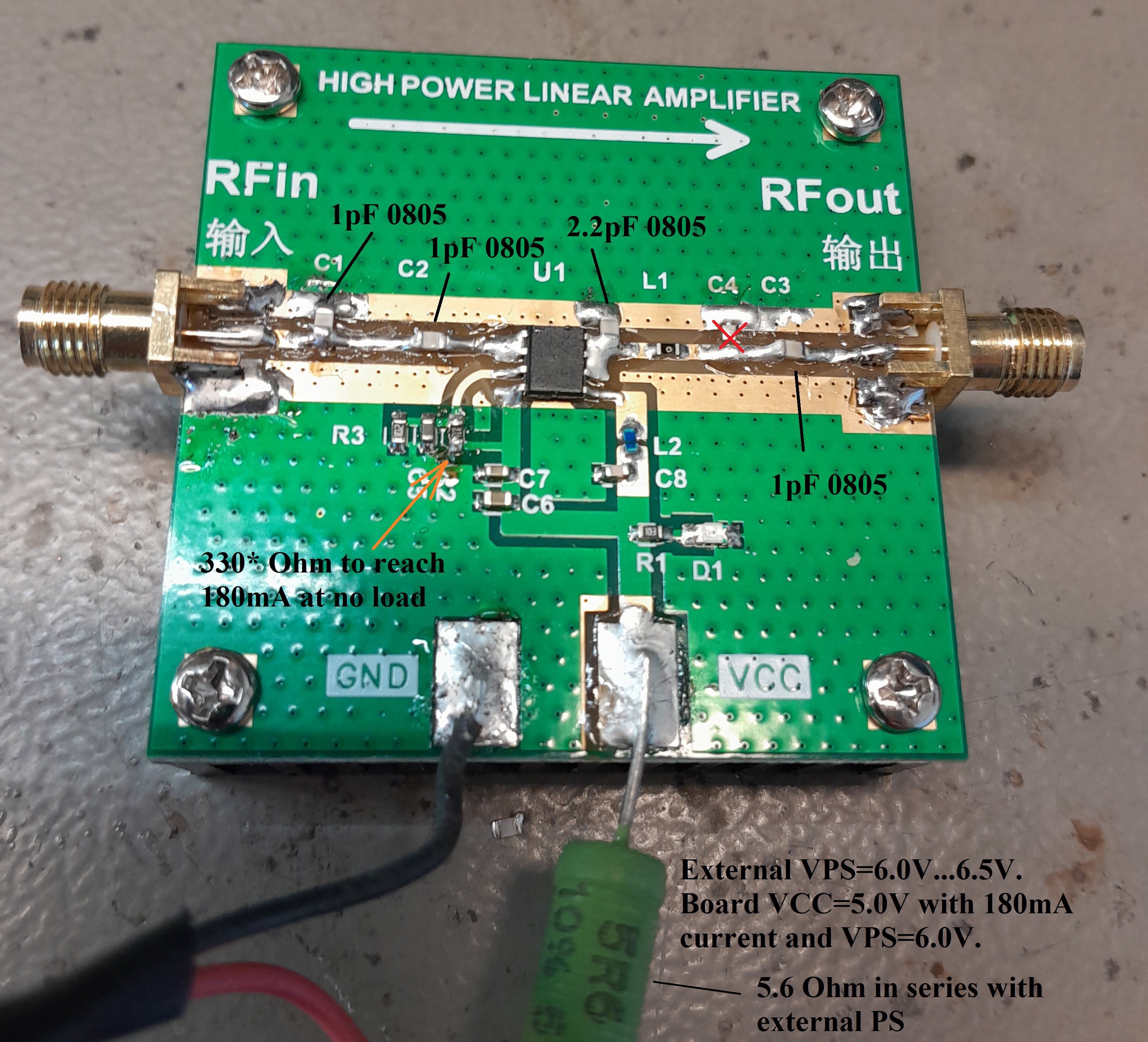
- The board should be supplied using a series resistor 5.6 Ohm (2-5W rated). Without this resistor, the RF2126 is easy to damage.
- The VCC should not be bypassed with a big low ESR capacitor. The energy of the electrolytic cap can easily damage the chip. Tantal capacitor might be OK but I did not use big caps at all. Thus, the PCB ceramist bypass caps are totally OK and enough.
- The resistor divider for pin 3 of RF2126 should be adjusted to have 180mA of supply current. It is exactly the recommendation from the datasheet.
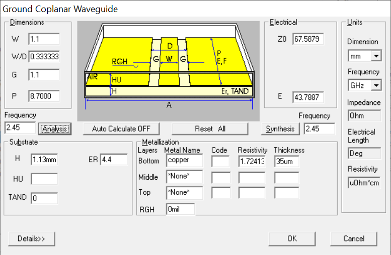
PCB stack-up notes
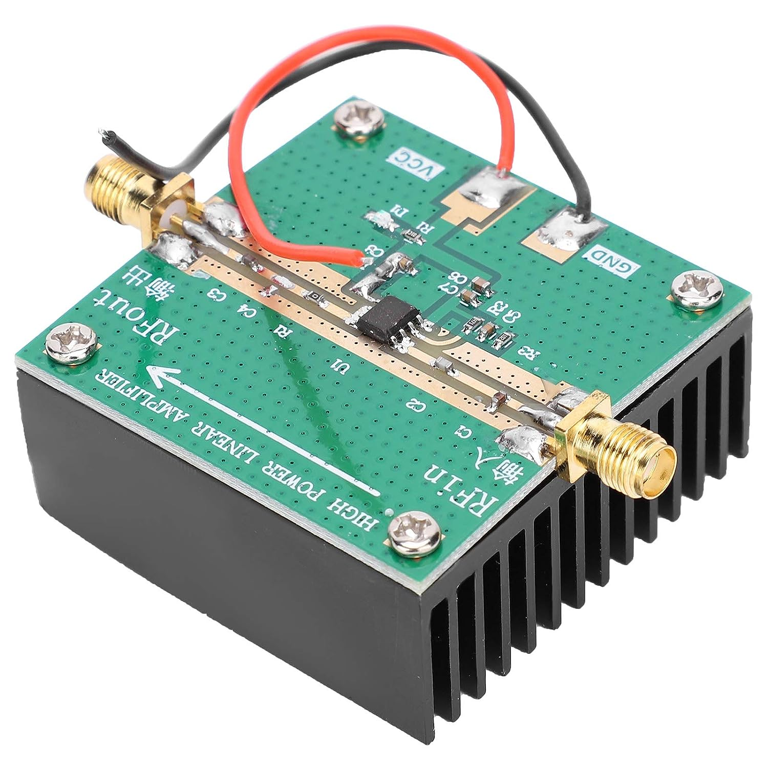
- PCB thickness is measured as 1.2 mm.
- Dielectric thickness is estimated as 1.13 mm.
- Transmission lines (TL) are performed as grounded coplanar waveguides with a track width of 1.1 mm and the same gap of 1.1 m.
- Apparently, the characteristic impedance is 67.6 Ohm instead of 50 Ohm expected.
Ansoft Designer SV simulation

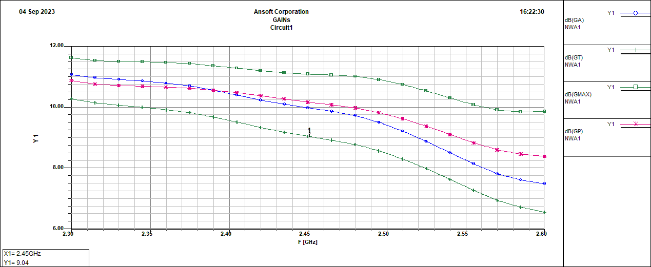
- Ansoft Designer SV simulates gains and impedances.
- GT is transducer gain - worst case with bad matching.
- GMAX - ideal maximum possible gain with input-output matched with source and load.
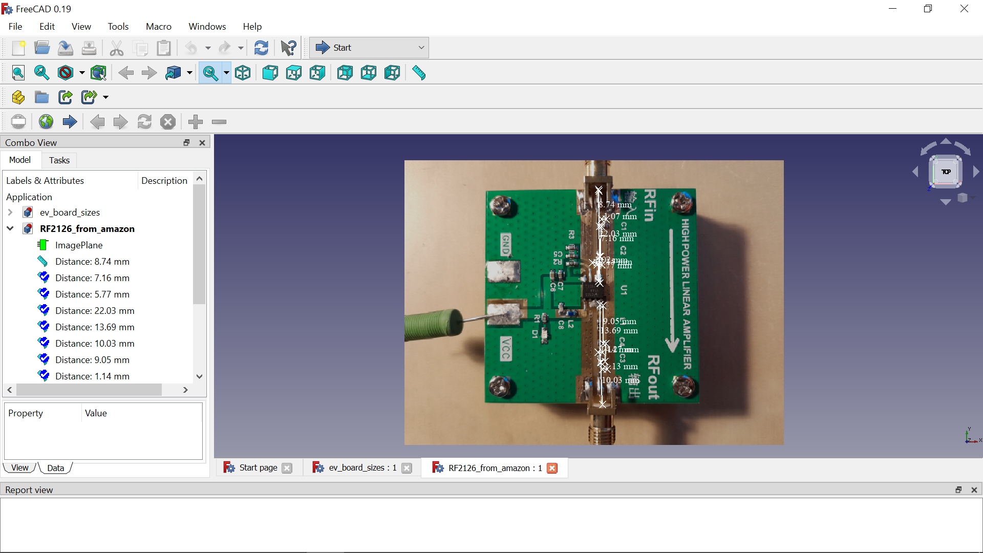
TL parameter extraction
- FreeCAD is used to measure TL lengths and track widths.
SPICE simulation - MicroCAP 12 optimization
- MicroCAP is free now and has a powerful feature like an optimizer.
- So, we are going to implement only additional MLCC capacitors and not RF inductors (I do not have them).
- The minimum capacitor I have is 1pF/1.5pF/2.2pF as part of the kit of 0805 capacitors.
- 0805 capacitor has approx. 1nH of parasitic ESL inductance that must be included in the model.
- Due to this ESL standard process of impedance matching is not possible since I did not have RF capacitors. Otherwise, an optimizer is not needed.
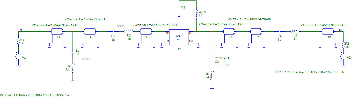
- So, now we put the capacitor model with series ESL. ESL is fixed to 1nH and capacitances can vary during optimization.
- TL electric lengths are extracted from Ansoft Designer simulation setup.
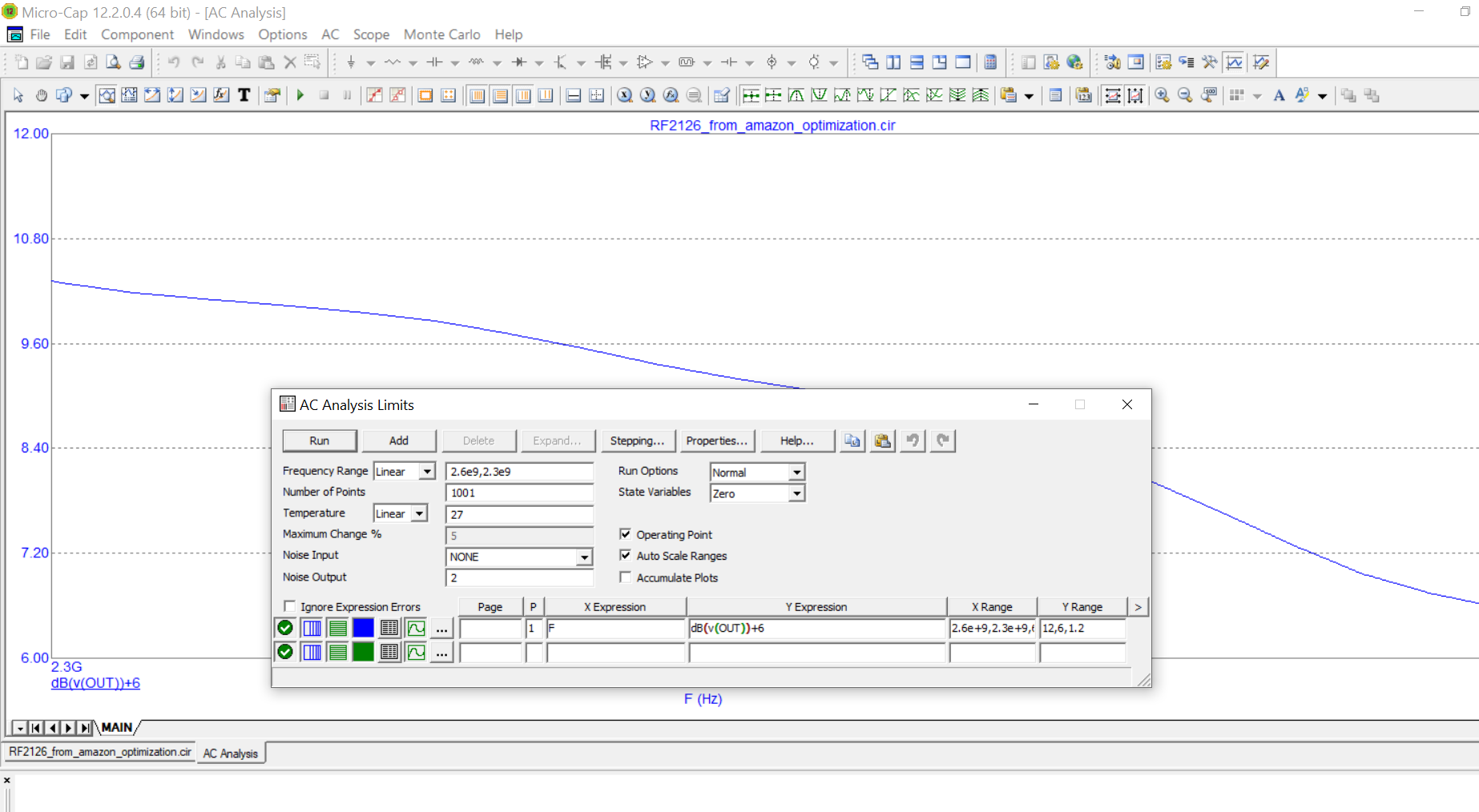
- dB(v(OUT))+6 corresponds to GT gain.
Optimization results
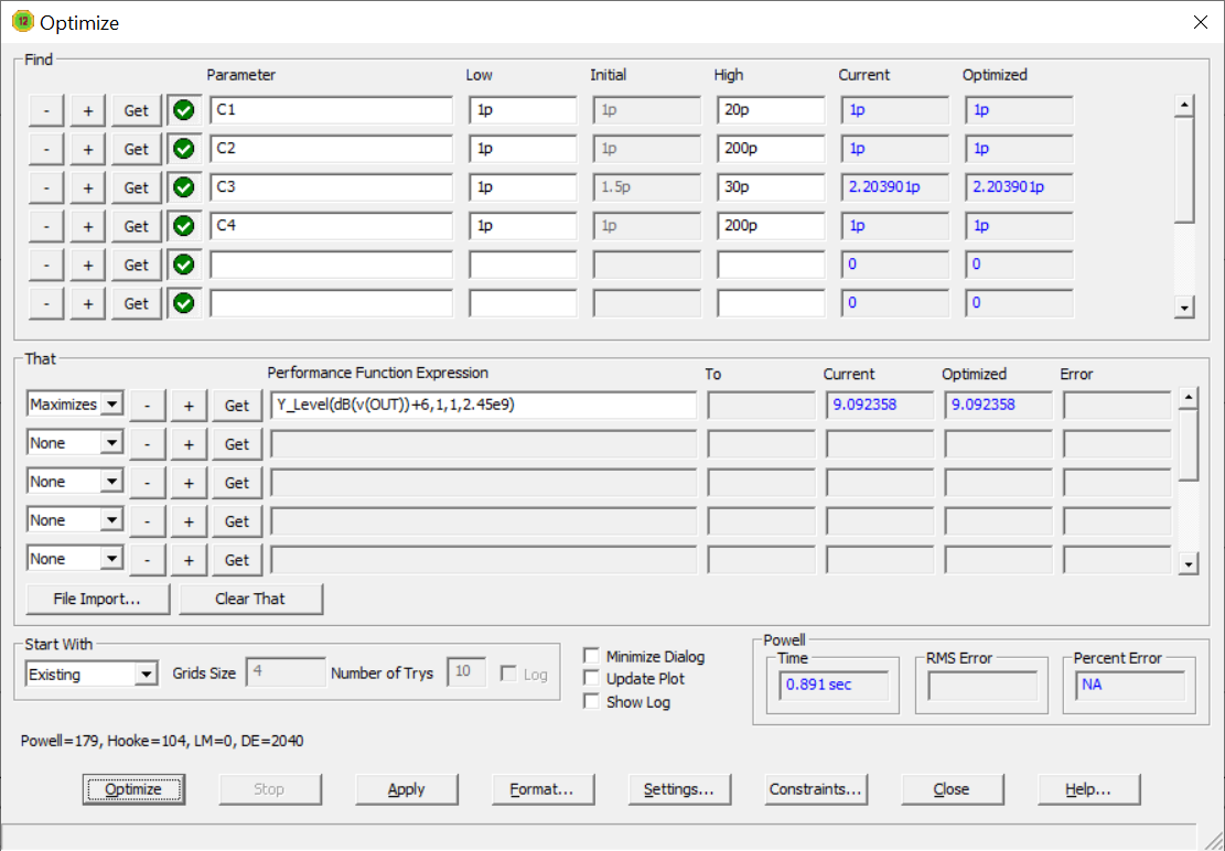
- 1pF as minimum capacitance available.
- 9dB as a result gain is obtained. It is only 2 dB less than ideal.
- Luckily, the resulting capacitance is very close to standard values (1pf and 2.2pf).
- if you have a good kit of capacitors like <1pF other settings are possible.
- MicroCAP and Ansoft Designer give the same results in AC analyses.
- The best result after optimization varying only caps is 9dB of gain.
- Theoretically, in accordance with S-parameters for RF2126, the maximum achievable gain is 11 dB, but to reach it more complex matching networks are necessary to implement (LC circuits, TLs etc.).
PCB modifications summary
- So we use the placed for cpacitances that are already on the PCB exept one that is mounted directly on the RF2126 output (2.2pF).
- C1=C2=C3=1p and C4=NM.
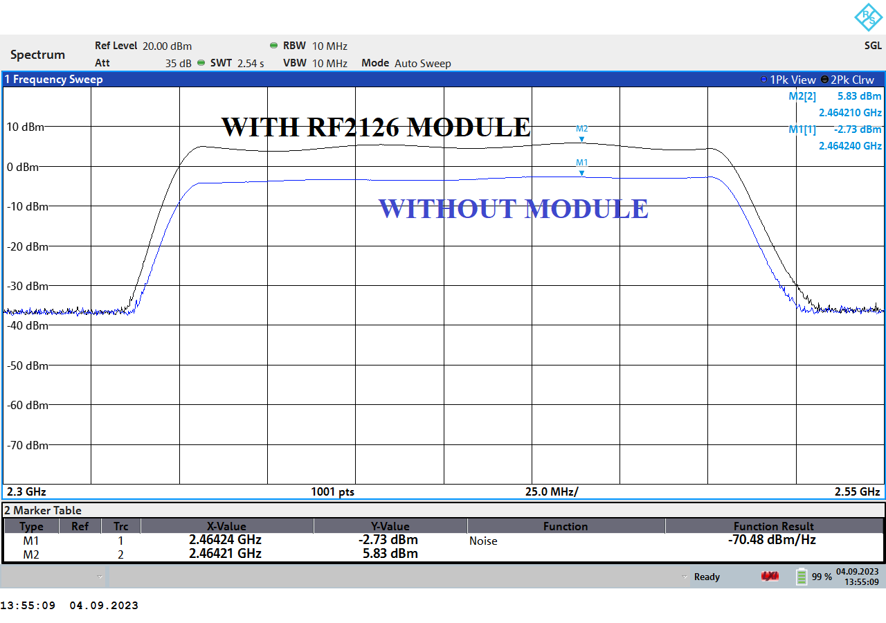
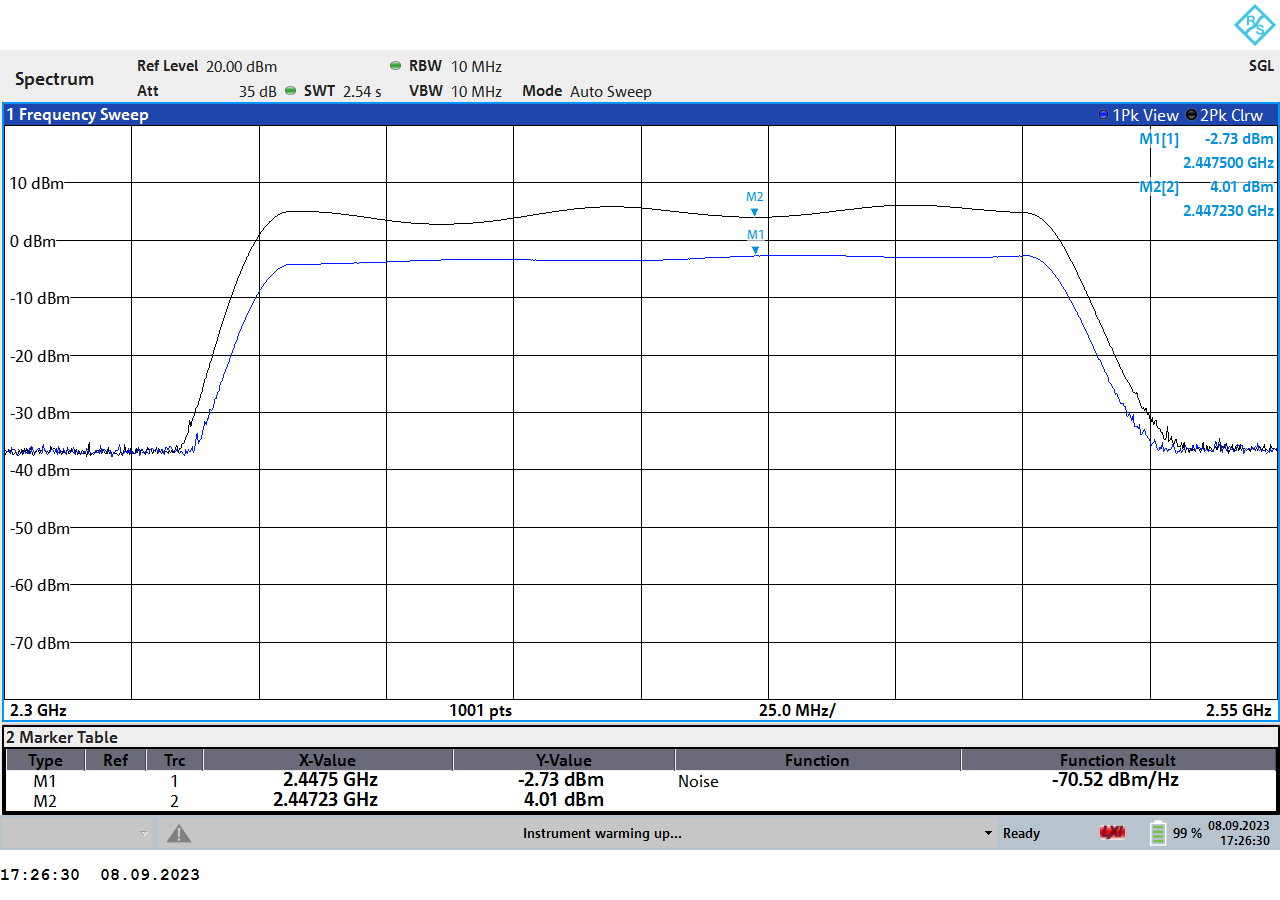
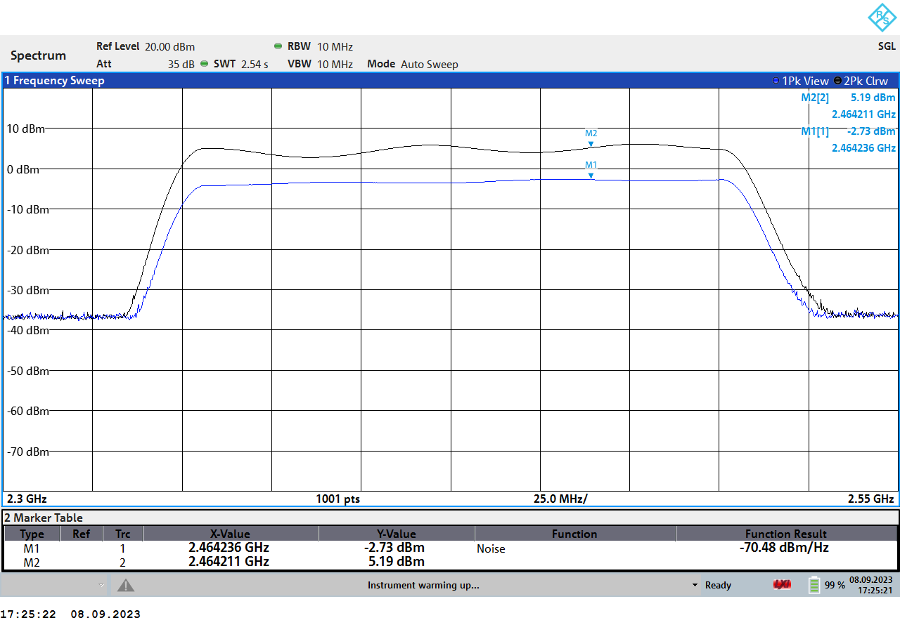
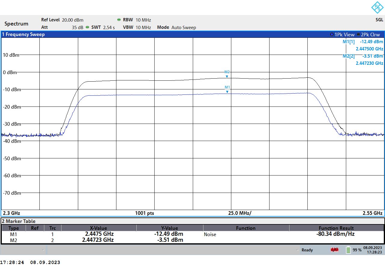
Experiment
- 20dB attenuator at spectrum analyzer input.
- 10dB attenuator at RF2126 module input improves gain flatness, so seems like the signal generator source impedance is not perfectly equal to 50 Ohm. See the log for the second module modification results.
- The result might be 1dB better, one cable (1m) extra with module measurement.
- The gain measured around 8.5...9 dB which is a good match with the simulation.
Useful links
http://www.dj9kw.de/dj9kw/projekte/afu/RF2126_13cm_PA/rf2126.htm
https://www.pittnerovi.com/jiri/hobby/electronics/hf/index.html
References
- Circuit Design for RF Transceivers by Domine Leenaerts, Johan van der Tang, Cicero S. Vaucher
- https://www.avx.com/docs/techinfo/CeramicCapacitors/parasitc.pdf

 Denis
Denis
 Michele Perla
 Dilshan Jayakody
 Thomas