 Michael Wessel
PicoRAM 2090
A Raspberry Pi Pico (RP2040)-based 2114 SRAM Emulator and Multi-Expansion for the Busch
2090 Microtronic Computer System.
Final Demo Video on YouTube:
I have written about the Microtronic here before, and done a few Microtronic-related projects:
- https://hackaday.io/project/11560-the-talking-microtronic-computer-system-emulator
- https://hackaday.io/project/176466-microtronic-the-next-generation
- https://hackaday.io/project/180252-a-retro-authentic-microtronic-emulator
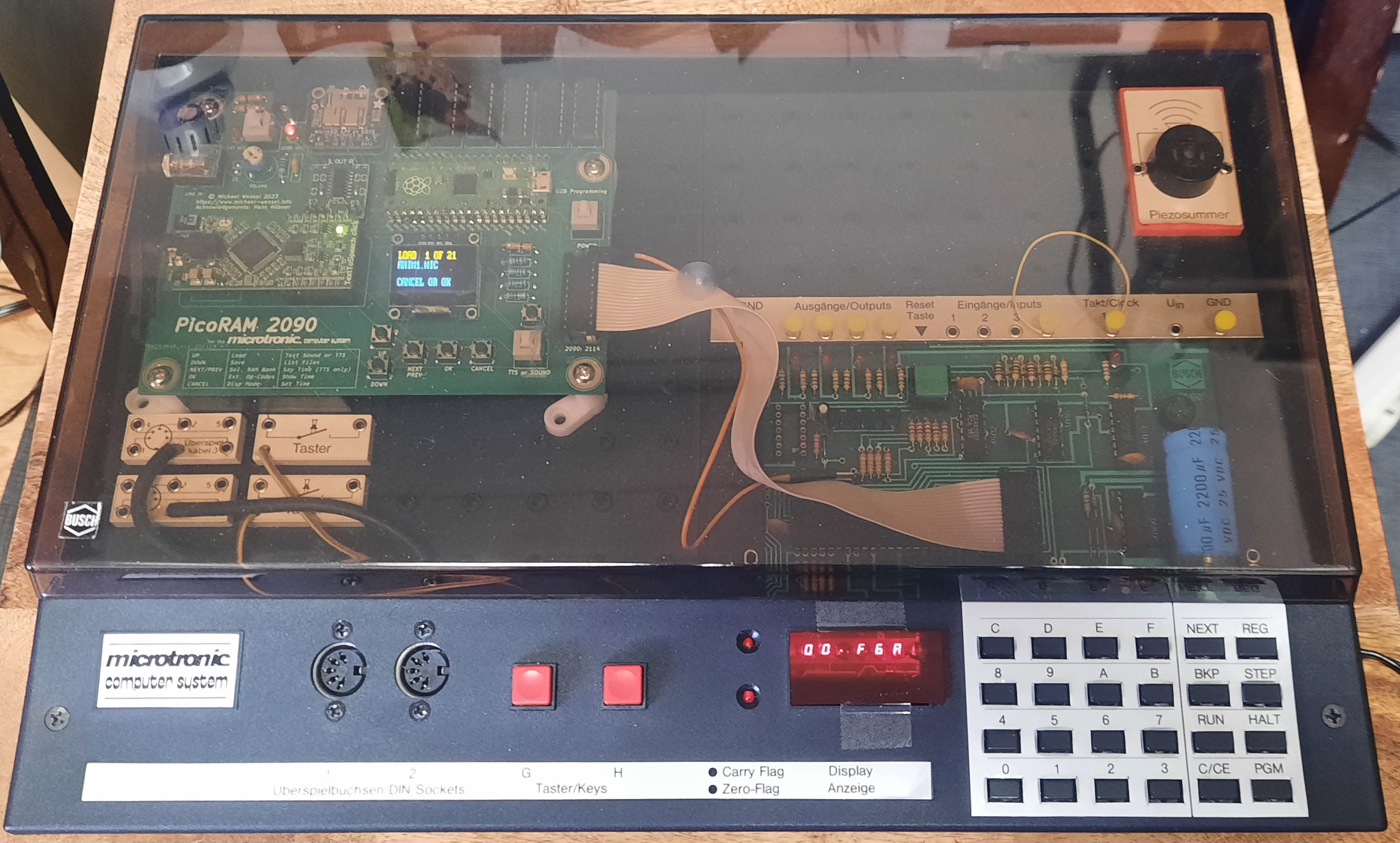
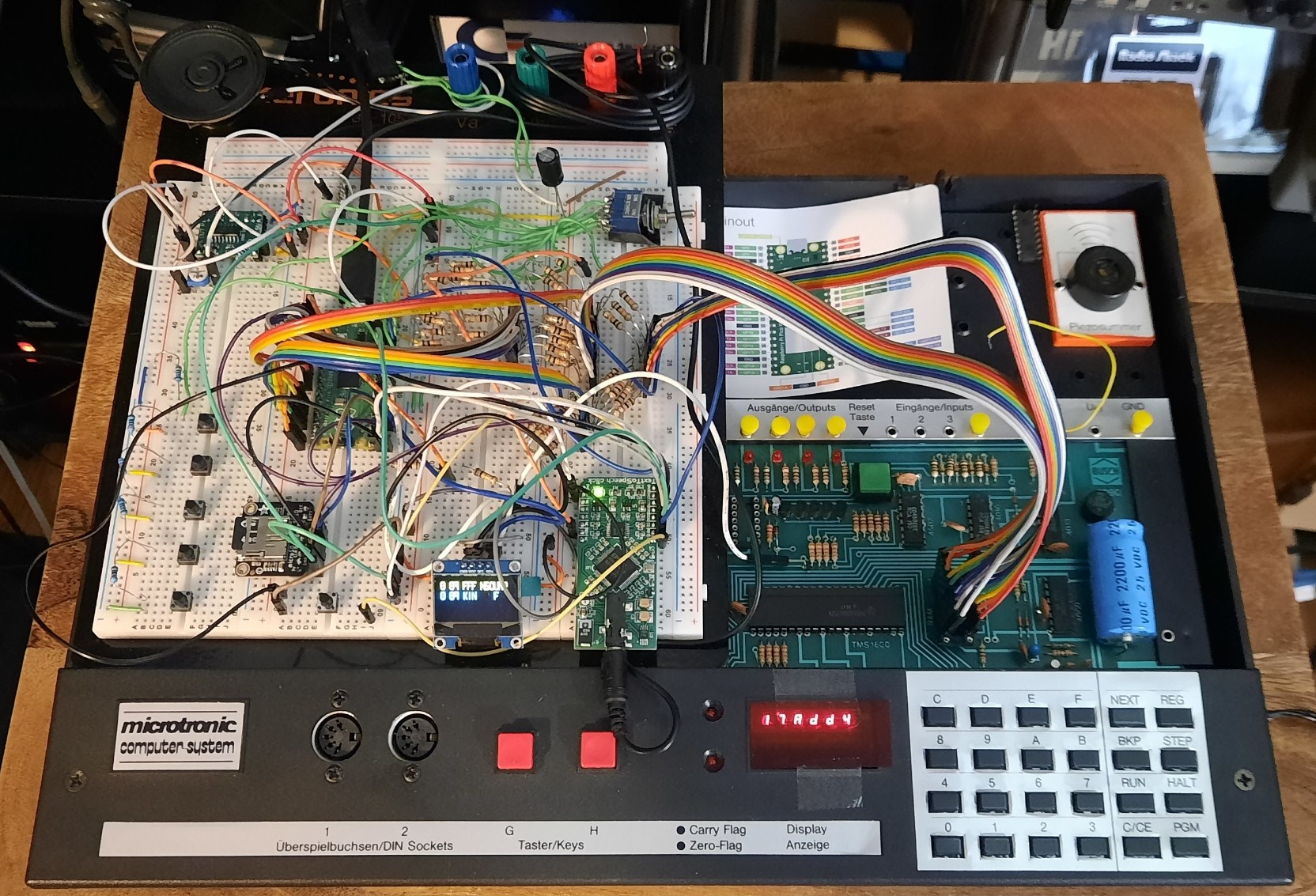
The final PicoRAM 2090 in the Microtronic:


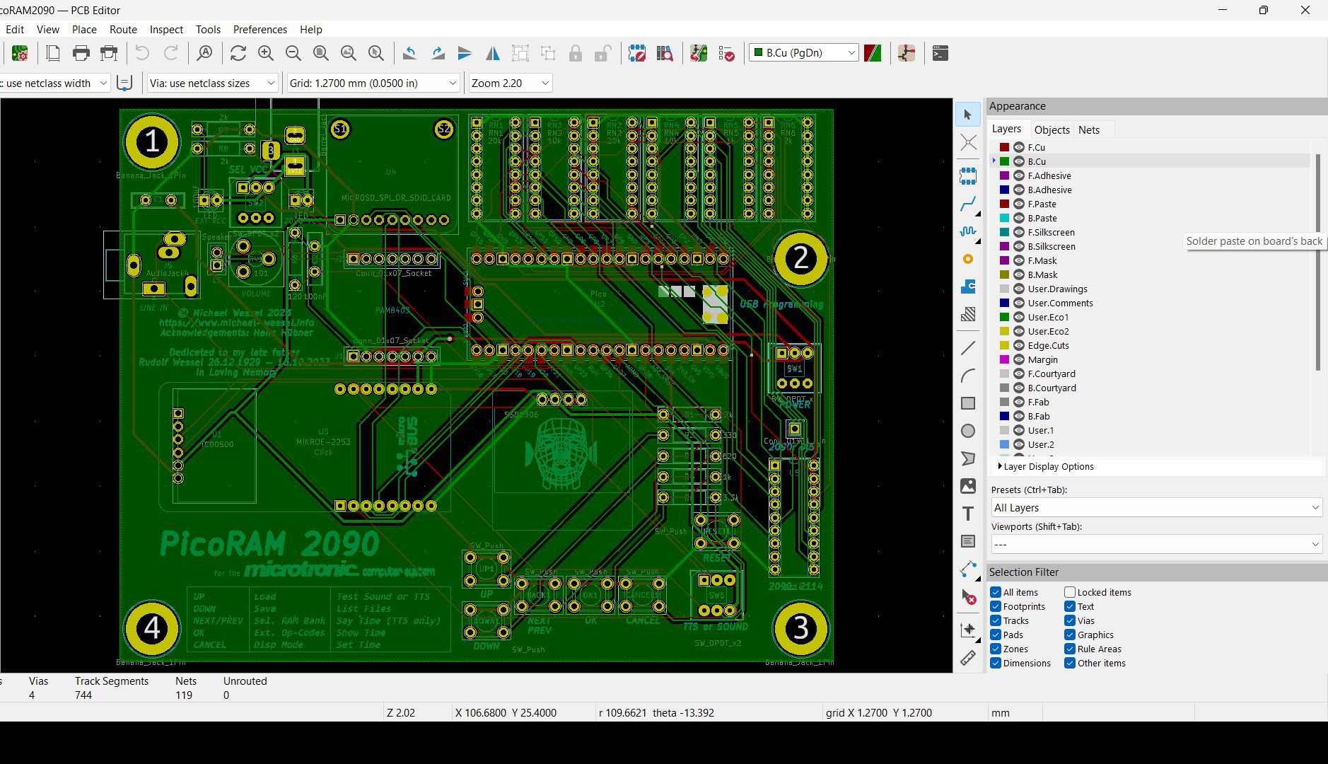
The firmware is attached to the project, as are the Gerber files. Please also have a look at the Github repo.
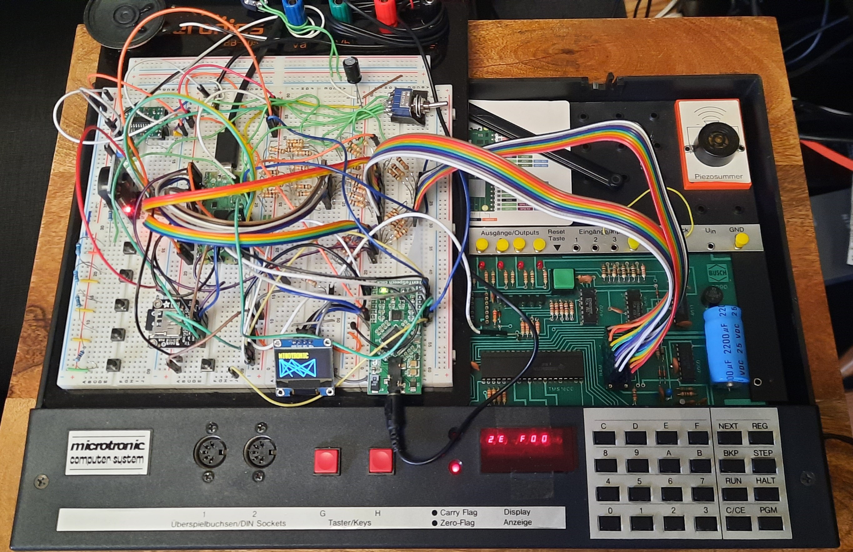
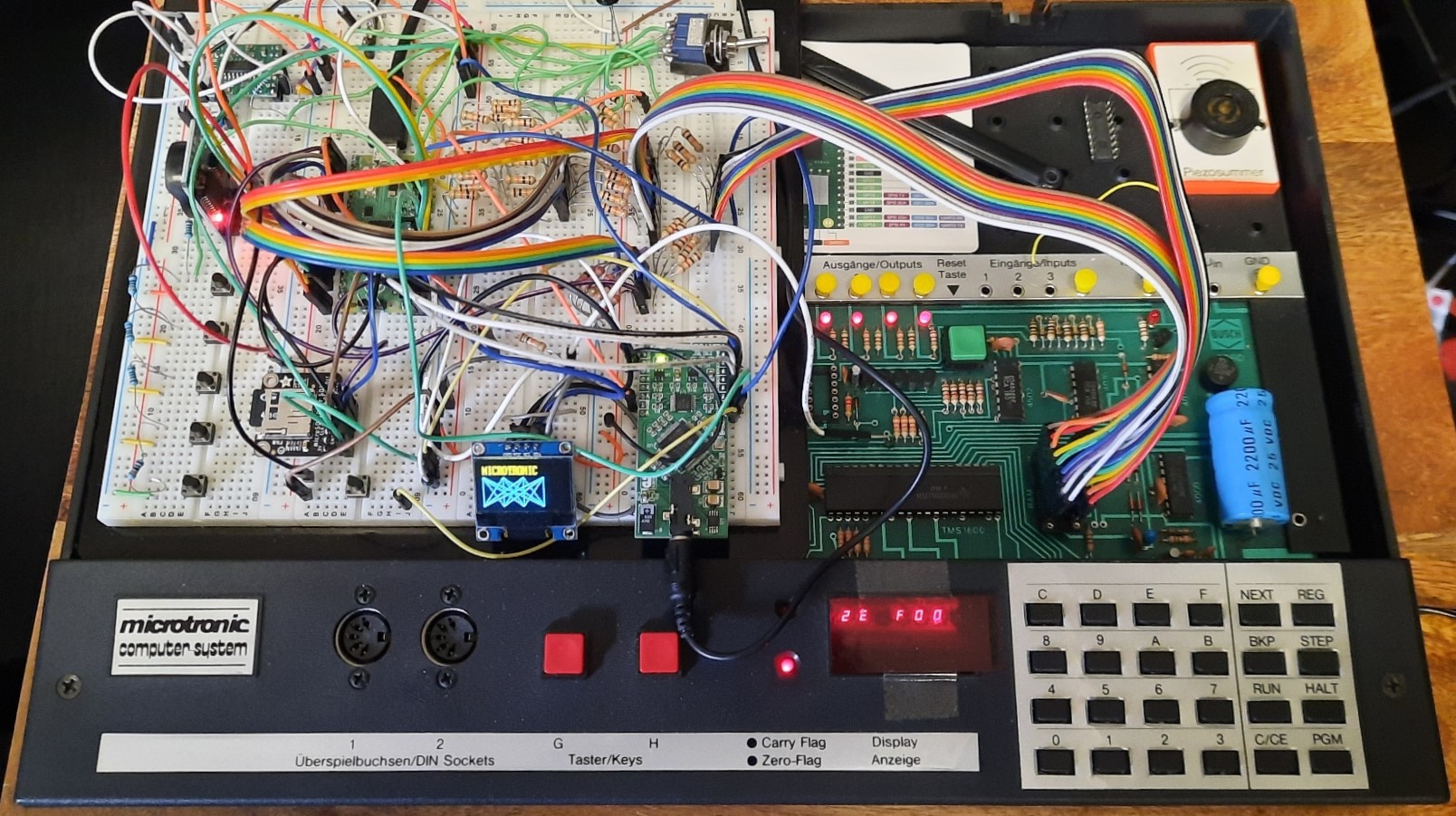
Early Prototype Pictures: 
Latest News / Updates
It's done! PicoRAM 2090 is finished. The GitHub repo has been updated and now contains an extensive README, the Gerbers, and the firmware. I'll upload the source code a little bit later. But for now, Makers / builders have everything they need to replicate it!
Here's the final demo video on YouTube:
Log Entries for RetroChallenge 2023/10 Participation
It's done - the RetroChallenge 2023/10 October month is coming to an end! This is my final video for the challenge which wraps it up - a full demo of most of the implemented features (with the exception of the RTC - see Log Entry 4 for that instead). I implemented everything I promised here: https://www.retrochallenge.org/2023/10/rc202310-halftime-update.html
All RetroChallenge 2023/10 Log Entries
Some more details in the final RetroChallenge log entry: https://hackaday.io/project/192655-picoram-2090/log/224691-retrochallenge-202310-log-entry-6-final-wrap-up-demo-video
DS3231 Real Time Clock: https://hackaday.io/project/192655-picoram-2090/log/224507-retrochallenge-202310-log-entry-5-ds3231-for-microtronic
Text, Speech, & Graphics Demo: https://hackaday.io/project/192655-picoram-2090/log/224486-retrochallenge-202310-log-entry-4-demo
Extended Op-Codes, Bank Switching: https://hackaday.io/project/192655-picoram-2090/log/224467-retrochallenge-202310-log-entry-3
SD Card Memory Dumps: https://hackaday.io/project/192655-picoram-2090/log/224327-retrochallenge-202310-log-entry-2
Overall Idea and Setup: https://hackaday.io/project/192655-picoram-2090/log/224259-retrochallenge-202310-log-entry-1
By now, the SD card interface, banked memory, graphics, text, speech, and sound extensions are working! Here is a little demo:
About
This project started out as an attempt to emulate the 2114
SRAM found in the Busch
2090 Microtronic Computer
System - a fully
compatible "drop in" replacement using the Raperry Pi Pico. A Pico-based SRAM emulator facilitates SD card-based storage of Microtronic memory dumps / its program memory, and hence of programs. Saving to and loading back of programs to SD card is much faster and more convenient than the Microtronic cassette interface (also, the files can be edited and created on the PC / Mac).
Later, this project became more ambitious - utilizing the first core of the Pico for SRAM emulation, the second core is now being used to implement a co-processor / IO extension for the Microtronic. By now it features a banked memory expansion (16 memory banks!), OLED text and graphics output, speech, and sound output. See the latest video above for a short demo.
Original Background & Context / Historical Account of the Project
This is the Microtronic Computer System from 1981, a 4bit educational computer - on the left you see the cassette interface. It also has an Arduino-based speech synthesizer connected to its output ports (an older project of mine, ~ 2016):

The 2114 was a popular and widely used 1024x4 Bit SRAM chip. It was used in many early arcade games from the late 1970s and early 1980s. Pinout:

The Microtronic is a relatively slow educational 4bit microcomputer,
so timing is not critical. A standard Pico is more than fast enough
for the Microtronic. Note that the Microtronic doesn't utilize the
CS (Chip Select) line of the 2114; only WE (Write Enable) is used
in addition to the 10 address lines (A0 to A9) and 4
data lines (IO/1 to IO/4).

Hardware Setup
The wiring goes as follows:
GP2..GP11: address linesA0..A9(input)GP12..GP15: data linesIO/1..IO/4(input/output)GP22: Write Enable (WE), low active (input)
Simply connect the corresponding Pico GP ports to the corresponding
2114 pins; in the original Microtronic, the 2114 is housed in a
special (white) socket, so the chip is easily spotted:

I recommend replacing this socket with a standard DIP socket so that the PicoRAM 2090 can be connected more easily. I simply used DuPont cables and a standard (machined) IC 18pin DIP socket; DuPont cables plug in very firmly and permanently into these.

You'll need 3.3V to 5V (TTL) level converters.
For this setup, I simply used a FREENOVE Breakout Board for Raspberry Pi Pico which I thought already had level converters on board, but this turns out to be not the case (thanks, Hans!) So you should still add level converters; this setup is probably not entirely safe and might damage your Pico in the long run.

A Safer Version
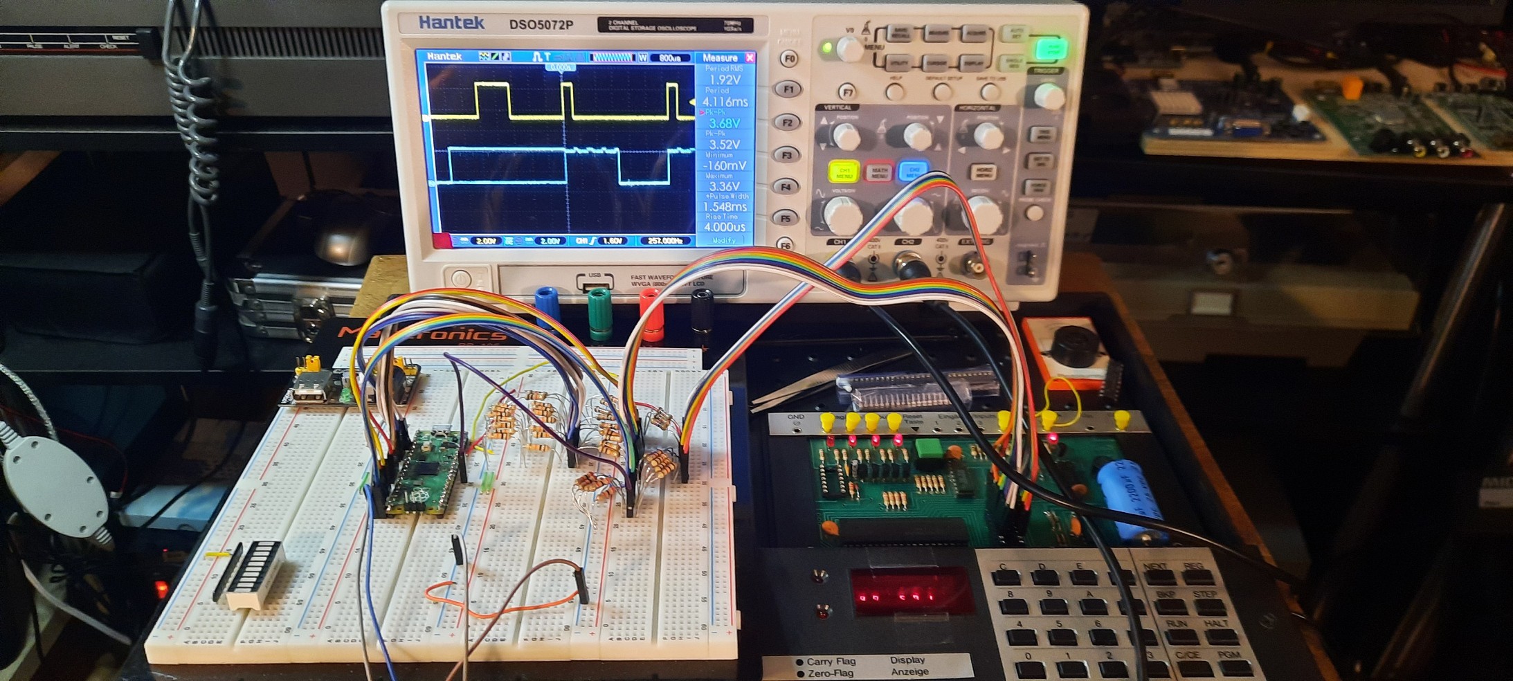
Whereas the version without the level shifters works, it is probably not the safest option for Pico longevity. Looking at the oscilloscope, the peak voltage levels are indeed much too high. Even though the Pico doesn't seem to care too much (it was running for hours without damage), it's well out of spec, and probably it won't last very long like this:


Hence, level shifters!
I experimented quite a bit with various 3.3 - 5.5 V active level shifters, utilizing the TXS0108E as well as the ones with discrete MOS-fets with pull-up resistors. None of them worked for the Microtronic.
I eventually realized that this is due to the unusual hardware setup in the Microtronic. See, the TMS1600 GPIO lines that address the 2114 (inputs into A0 to A9) are also used for multiplexing the 7segment LED display, as well as for keyboard matrix scanning!
Moreover, there is no CS signal which would allow me to distinguish the "real" RAM accesses on O0 - O3, R1 - R5 from the "inadvertent" accesses that occur due to LED display and keyboard scanning activity. In fact, the 2114 just outputs its data for these "addresses" as well, but they are simply ignored (after all, the firmware of the Microtronic knows when to read the addressed RAM, and when not to).
One can see in the Schematics that the output lines specifying the addresses for the 2114, O0-O3, R1 - R5, are connected to 33 kOhm pull-down resistors. The electrical levels I got from the off-the-shelf level converters simply were not compatible with that - these level converters feature a 5V pull-up resistor, pulling these lines to high, whereas the pull-down resistors on the Microtronic are doing the opposite.
Encouraged by discussions with a fellow retro-enthusiast (thanks to Hans, again), I decided to go with simple voltage dividers for these address lines instead. I started with the standard 1k-2k divider, but this caused the LED display to malfunction - segments were now lightning up when they were not supposed to. To match the existing 33 kOhm pull-down resistors, we then found a 10k-20k divider which solved the problem for the address lines.
I then tried the same 10k-20k divider for the data lines. Unfortunately, the resulting data output signals from the Pico were then unreadable by the TMS1600. Even though the voltage levels were right, it seemed that the signal currents were now too low. I hence exchanged these with 1k-2k dividers, and finally everything started to work properly - resistor hell!
The peak-to-peak voltage levels are still a bit too high (~ 3.6 V), but we are getting there. I can do one more round of "resistor tuning":
This is obviously resistor / voltage-divider hell, but it's only an experimental breadboard, and I am going to design a proper PCB at some point when the project is ripe, and the planned features (see below) have been implemented. It's going to be a real product, eventually.
I feel much more comfortable with the voltage dividers in place now. This should protect the Pico sufficiently.
Firmware
Checkout
https://github.com/raspberrypi/pico-setup-windows;
Visual Studio Code (VSCode) for Rasperry Pi Pico. This installation
includes a set of Pico examples. Copy the files from the src
directory into a directory sram to your
pico-examples. Also add the add_subdirectory(sram) to the global
CMakeLists.txt in the pico-examples directory so that a Build All from VSCode will automatically generate it together with the
other examples.
After a build, you can simple copy the generated sram.uf2 (see the
build/sram sub-directory) to the Pico using the power-on reset USB
method.
YouTube Video
Emulating (S)RAM with the Raspberry Pi Pico!
Original Future Plans / Next Steps (Outdated, Check the GitHub Repo for Final Status!)
- add a display and enable save & load of SRAM images to EEPROM / SDCard, turning this into a powerfull SRAM-image based mass storage solution (no more cassette interface needed for saving and loading Microtronic programs)
- add capability to select different SRAM banks using Microtronic's digital output ports, turning this into a banked memory expansion for the Microtronic offering up to 15x more RAM!
- having a SHARED RAM between the Microtronic and the Pico enables interesting new features! See, the Pico could actually act as a co-processor - if it knew the current instruction the Microtronic is at, i.e., the value of the Program Counter (PC), it could do "something" autonomously with the current instruction. Obviously, it knows the RAM content. However, getting to know the PC is much complicated by the fact that there is no clear hardware signal, i.e., no CS as explained, and the address lines are also used for multiplexing the LED display as well as for keyboard matrix scanning. These result in involuntary SRAM accesses. Writes to the SRAM are easy to spot, sure (after all, we have the WE signal) - but that doesn't help for normal program execution. However,
- it might be possible for the Pico to infer the current PC by monitoring the SRAM accesses and identify certain characteristic access patterns that give away what's happening - i.e., I would assume that accesses to three consecutive SRAM addresses would result from retrieving (loading) the current instruction at the PC... If this is indeed a characteristic access pattern that can be identified, it should be possible to infer the PC. And idea to investigate for sure.
- if the Pico were able to determine the PC and hence the current instruction, some of the non-meaningful op-codes could be interpreted by the Pico to implement extra-semantics in terms of new side-effects. For examples, instructions of the pattern MOV <x> -> <x> (op-codes of the form 0xx), where x is one of the 16 4bit registers, copies register x to itself - a vacuous operation, and no real Microtronic program uses these op-codes. I have utilized these "vacuous", unused op-codes previously to implement extra-semantics in my Microtronic emulators: https://hackaday.io/project/176466-microtronic-the-next-generation and https://hackaday.io/project/180252-a-retro-authentic-microtronic-emulator I used them for speech and sound side-effects in the past.
- given that the Pico is managing and serving the Microtronic's program memory, this enables another interesting avenue previously blocked - self-modifying programs, or more generally, the ability to materialize arbitrary RAM content based on computation! Note that the Microtronic, by itself, is a Harvard-architecture, so traditionally all writable memory is register only (it has a large register file - two sets of sixteen 4bit registers). However, with the Pico for SRAM emulation in the loop, and the ability to introspect the current instruction and implement extra semantics, this road is now wide open!
- design a PCB